Table of Contents

Summary of Contents for Scantron Proscan 2200
- Page 1 Proscan 2200 User Manual Scantron Industrial Products Ltd Monarch Centre Venture Way Telephone: +44 (0)1823 333343 Taunton Fax: +44 (0)1823 333684 TA2 8DE e-mail: scantron@scantronltd.co.uk England Internet: www.scantronltd.co.uk...
- Page 2 Proscan 2200 (Chromatic Sensor) User Manual V.4.0 Documentation Version Version Created / Amended Author Notes 03/06/2020 Components Installed / Supplied Notes Sensor Type Stil Chromatic Sensor Stil Prima CCS Controller 7” Colour Sensor Display Camera USB / Firewire CMOS...
-
Page 3: Table Of Contents
Proscan 2200 (Chromatic Sensor) User Manual V.4.0 Table of Contents Introduction ......................... 4 1.1. Overview ....................... 4 1.2. Options ........................4 1.3. Mechanical Construction and Technology ............5 1.4. The Stand ......................5 1.5. Power Supply Module ................... 6 1.6. -
Page 4: Introduction
To accommodate clients’ specific needs, this manual may include references to sensors, cameras and display interfaces that have not been supplied / installed on a particular system. The sensors supplied with the Proscan 2200 system may incorporate one of two main types. •... -
Page 5: Mechanical Construction And Technology
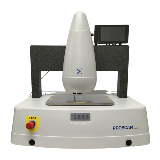
Proscan 2200 (Chromatic Sensor) User Manual V.4.0 1.3. Mechanical Construction and Technology The Proscan 2200 is suitable for the most exacting of applications, and uses the experience gained from more than 25 years to create, what is probably the best of its kind. -
Page 6: Power Supply Module
Proscan 2200 (Chromatic Sensor) User Manual V.4.0 1.5. Power Supply Module • Overall dimensions 430 mm x 350 mm x 140 mm max • Weight 6.1 kg • Electrical Specification 100-110 or 220-240 VAC, 50/60 Hz • (see product labelling) 1.6. -
Page 7: Sensor Display
Proscan 2200 (Chromatic Sensor) User Manual V.4.0 1.7. Sensor Display An optional dedicated sensor display may also be attached to indicate the current position in the sensor range. 1.8. Optical Pens The optical pen or optical probe is the measuring head sensor. -
Page 8: Installation Considerations
Proscan 2200 (Chromatic Sensor) User Manual V.4.0 2.0 Installation Considerations 2.1. Environment The stand contains both mechanical and electronic components. It should be located in a sheltered, dry environment with temperatures controlled within 10 to 35 degrees C. Care should be taken to prevent excessive dust ingress, this may enter electrical and mechanical components with adverse effects including excessive mechanical wear, clogging of cooling fins etc. -
Page 9: The Power Supply Module
Proscan 2200 (Chromatic Sensor) User Manual V.4.0 2.3. The Power Supply Module The PSU Module contains power supplies and mains / DC power distribution. It needs to be installed in close proximity to the stand as the interconnecting cables are 3 m long. Generally the PSU Module is situated alongside the stand. -
Page 10: Connecting The System
Proscan 2200 (Chromatic Sensor) User Manual V.4.0 3.0 Connecting the System 3.1. Overview The following section describes the connection sequence. 3.2. Communication cables The system is supplied with all communication cables These include: • RS232 Sensor communication between Proscan and CCS controller •... -
Page 11: Connections To The Rear Of The Psu Module
Proscan 2200 (Chromatic Sensor) User Manual V.4.0 3.3. Connections to the rear of the PSU Module Before connecting the main power umbilical to the PSU Module, please ensure that the system is disconnected from the electricity supply. A basic system PSU Module, will look similar to the following illustration: - Connect the stainless steel sheathed power cable labelled ‘PSU POWER’... -
Page 12: Main Power Connection
Proscan 2200 (Chromatic Sensor) User Manual V.4.0 3.5. Main Power Connection Once the cables are all firmly connected and suitably supported, power can be applied to the system, via the 10 Amp fused IEC connector on the rear panel of the PSU Module. A spare 20mm T 10A fuse is located in the connector fuse carrier, should it be required. -
Page 13: Switching Off
Proscan 2200 (Chromatic Sensor) User Manual V.4.0 Double clicking on the above icon will result in the following sequence of events:- • The Proscan splashscreen will be displayed. • The Z drive axis will move vertically upwards until it finds its home position. It will then move a short distance back down (only if Z drive homing is enabled in software). -
Page 14: Changing The Sensor
4.1. Removing the Nose Cone To change sensor on the Proscan 2200, the nose cone must first be removed. Grip the nose cone on each side and lift towards you and upwards, off the machine. The nose cone rests on two rods which protrude from the z drive, these locate in the slots on the rear of the nose cone. -
Page 15: Changing 'S' Type Sensors
After fitting an ‘S’ type sensor to the Proscan, ensure that the correct sensor is selected on the ‘S’ type control unit. Select the correct sensor in the Proscan 2200 software. Before taking measurements, allow the sensor to :- •... -
Page 16: Dark Referencing
Proscan 2200 (Chromatic Sensor) User Manual V.4.0 Once the sensor has been changed, replace the nose cone. Select the appropriate sensor via the Tools/Sensor Selection menu in the Proscan 2200 software. 5.0 Dark Referencing 5.1. Acquiring the dark signal The dark signal of the sensor is generated by undesirable back-reflections on the optical surfaces inside the sensor. -
Page 17: Manual Z Height Control Buttons
Proscan 2200 (Chromatic Sensor) User Manual V.4.0 6.0 Manual Z Height Control Buttons On the front of the Proscan Base there are four buttons to manually set the ‘Z’ axis height of the sensor. This assists the placement of the sample to be scanned and then setting the initial height of the sensor relative to the sample for optimum scan range. -
Page 18: Routine Maintenance
Proscan 2200 (Chromatic Sensor) User Manual V.4.0 8.0 Routine Maintenance Scantron recommend an annual system Verification and routine maintenance regime be adopted. Part Description Period Z axis lead-screw Apply THK multipurpose lithium EP grease Every 12 months to lead-screw X and Y rails... -
Page 19: Troubleshooting
Proscan 2200 (Chromatic Sensor) User Manual V.4.0 9.0 Troubleshooting Fault Possible reason Action On double clicking software Electronics enclosure not Plug in and switch on icon, splash screen showing plugged in/switched on ‘Scantron Proscan 2000’ Stand stop pushed in Pull stop firmly to out position, press ‘Esc’... - Page 20 Proscan 2200 (Chromatic Sensor) User Manual V.4.0 out. Close Proscan software, power cycle the embedded PC, and re-start Proscan software Z drive does not go home Inhibit z drive set in software In Tools/Configure there is a setting ‘inhibit Z homing’. With...
-
Page 21: Declaration Of Conformity
Proscan 2200 (Chromatic Sensor) User Manual V.4.0 10.0 Appendix A 10.1. Declaration of Conformity EC – DECLARATION OF CONFORMITY We, as the manufacturer, declare under our sole responsibility, that the product listed below to which this declaration relates, is in conformity with the following standard(s) or standardisation documents DIN EN 60825-1:2014 Laser classification. -
Page 22: Contacting Scantron
Proscan 2200 (Chromatic Sensor) User Manual V.4.0 10.2. Contacting Scantron Postal Address: SCANTRON INDUSTRIAL PRODUCTS LTD Monarch Centre Venture Way TAUNTON Somerset TA2 8DE England Telephone: +44 (0)1823 333343 Fax: +44 (0)1823 333684 e-mail: scantron@scantronltd.co.uk Internet: www.scantronltd.co.uk... -
Page 23: Warranty
Taunton, England. Shipping and packing charges are to be paid by the buyer. Whenever the size or type of the equipment are such that it cannot be easily shipped, Scantron will despatch spare parts and service personnel to the buyers facility to carry out the repair at its own expense. -
Page 24: Basic System Components
Proscan 2200 (Chromatic Sensor) User Manual V.4.0 11.0 Appendix B 11.1. Basic System Components PSU Module Stand Dell PC Dell keyboard, USB connector Dell mouse, USB connector Dell 22” Widescreen LCD monitor IEC Power leads. Monitor cable, 1.5 m, with 15 way high density M/M ‘D’ connectors Power umbilical, 3 m cable, stainless steel sheathed.
Need help?
Do you have a question about the Proscan 2200 and is the answer not in the manual?
Questions and answers