Table of Contents
Advertisement
Quick Links
January 2022
Auto Fan Control with Demand Control Ventilation™
Installation, Operation, and Maintenance Instructions
Description:
The Larkin Auto Fan Control with Demand Control Ventilation™ will automatically energize the fan(s) prior to
cooking operations commencing per IMC code 507.1.1 by means of a temperature sensor and modulate the
fan(s) based on cooking load and building pressure.
System Components:
The Larkin Industries AFC-DCV (Auto Fan Control with Demand Control Ventilation™) wall mount control
box includes the following:
•
Wall mounted 18" x 26" x 8" stainless steel enclosure with hinged door and tamper resistant latch.
•
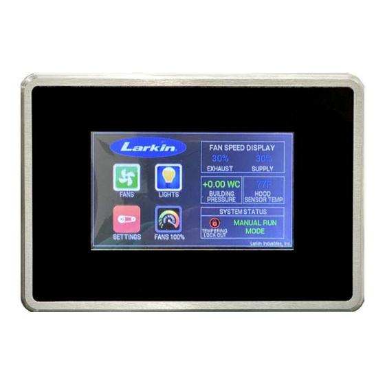
Color touch screen display mounted on enclosure door for system operation.
•
Exhaust and Make Up Air (MUA) fan(s) are interlocked. If hood fire suppression system is activated, the
lights and MUA fan(s) shut down. The Exhaust fan(s) will continue to operate at 100%.
•
Temperature sensor(s) factory mounted in hood(s).
•
Exhaust and MUA fan VFD(s) (Variable Frequency Drive). * Fans must be 3 Phase *
•
Prewired with terminal strips and wiring diagrams.
Note: Wall mounted box size 18" x 26" x 8" for up to 6 VFD's.
For technical support contact Larkin Industries, Inc.
1-800-322-4036
1
Advertisement
Table of Contents

Subscribe to Our Youtube Channel
Summary of Contents for Larkin AFC-DCV
- Page 1 Installation, Operation, and Maintenance Instructions Description: The Larkin Auto Fan Control with Demand Control Ventilation™ will automatically energize the fan(s) prior to cooking operations commencing per IMC code 507.1.1 by means of a temperature sensor and modulate the fan(s) based on cooking load and building pressure.
- Page 2 Mounting • The AFC-DCV Control Box will be housed in an 18” x 26” x 8” stainless steel enclosure and should be secured to a fixed wall near the exhaust hood(s) it controls (Fig. 1). NOTICE: The VFD’s produce heat and must have proper ventilation.
- Page 3 Figure 3 Connections Required for System Larkin S/S 18” x 26” x 8” AFC-DCV Control Box with hinged door and color touch screen display: - Low Voltage wiring to hood sensor(s) - Wiring to lights in hood(s) - Fire suppression micro switch wiring...
-
Page 4: Wiring Instructions
Hood Mounted Temperature Sensor When the Larkin AFC-DCV is ordered with a Larkin Industries hood model, the temperature sensor will be factory mounted in each hood, so no field installation is required. Any AFC-DCV ordered for a non-Larkin hood(s), or Retro-fit application, the temperature sensor(s) will have to be field installed in each hood controlled by the system. - Page 5 1. Check the power source to see if it is compatible with the requirements of the provided system. The AFC- DCV wiring diagram lists the proper phase, voltage, and amp load. 2. Verify input power voltage before connecting to Variable Frequency Drive(s) (VFD). 3.
- Page 6 DCV functions of the system will not be active for that sensor. Micro Switch: The Larkin AFC-DCV requires a Fire Suppression System Micro-Switch connection. The Micro- Switch should be field wired from the Fire Suppression System to the Control Box connecting the Common (C) lead from the Micro-switch to the Fire Switch Common (FSC) terminal in the Control Box.
- Page 7 Connect the ¼” tubing (provided) to the Outdoor Pick-Up as direct as possible to the Control Box. Larkin recommends the tubing be enclosed in conduit from the Control Box to above finished ceiling. Conduit should also be used when penetrating walls or roof. Insert the tubing through the hole in the knockout located in the top of the Control Box.
- Page 8 50% volume. This connection allows the Control Box to lock out the heat/cool function of the unit when the turn-down is below 50%. When a Larkin Industries Tempered MUA unit is provided, use low voltage wiring from terminal R and W1 in the Control Box to terminals R and W1 in the Tempered MUA control panel.
- Page 9 Shunt Trip Breaker Connection: Field install wiring from the Control Box terminal Shunt Trip Hot (STH) to the trip terminals on the shunt trip breaker (a neutral may be supplied from breaker panel). This will provide 120V 1 PH power to trip the breaker in Fire Mode. WARNING: DO NOT APPLY VOLTAGE TO TERMINAL STH. THIS WILL CAUSE DAMAGE TO THE FIRE RELAY.
-
Page 10: Installation Checklist
“Off in Fire”. At the same time, NO2 and NO3 will close in Fire Mode supplying the connected voltage to those terminals for “On in Fire” (See Pg. 9). For technical support contact Larkin Industries, Inc. 1-800-322-4036 System Startup Turn on all breakers that power the fan VFD(s), Control Box power, hood lights. - Page 11 If the fan(s) and light(s) come on and “Auto Run Mode” is displayed, the temperature sensor in the hood has detected a temperature rise. If only the Exhaust fan(s) come on immediately and “FIRE” mode is displayed, check for proper connection of Fire System Micro-Switch (See Pg. 6) or check that the Fire Suppression system is not in the discharged position.
- Page 12 VFD Keypad: The keypad is an easy means for diagnostics of the VFD(s). The keypad is simply connected to the diagnostic interface on the front of the VFD(s). The AFC-DCV is supplied with one keypad and is interchangeable between VFD’s during operation for diagnostics. Note: The VFD(s) are pre-programmed per your job specifications prior to leaving the factory and should not require additional programming.
-
Page 13: Test Procedures
15 minutes after the first appliance under the hood has been turned on. The AFC-DCV (Auto Fan Control with Demand Control Ventilation) will accomplish this by automatically activating the fan(s) and light(s) anytime a hood sensor detects a rise in temperature. -
Page 14: Maintenance
800- 322-4036. The AFC-DCV system is designed to shut down the light(s) and MUA fan(s) and continue to run the Exhaust fan(s) in the event of fire and activate two Normally Open/Normally Closed (NO/NC) spare dry contacts (may be used for building alarm, horn strobe, etc.). - Page 15 *************************************************************************************************** (See Pg. 6) ***************************************************************************************************...
Need help?
Do you have a question about the AFC-DCV and is the answer not in the manual?
Questions and answers