Table of Contents
Advertisement
Quick Links
Advertisement
Table of Contents

Related Manuals for Suntex PC-3100

Summary of Contents for Suntex PC-3100
- Page 1 PC-3100/3100RS Operation Manual Microprocessor pH/ORP Controller...
-
Page 2: Table Of Contents
4.1 Illustration of rear panel 4.2 Illustration of terminal function 4.3 Description of terminal function 4.4 Installation of transmitter PH-300T 4.5 Connection of controller PC-3100 and transmitter PH-300T 4.6 Typical wirings 4.7 Illustration of electrical connection Configuration 5.1 Illustration of front panel 5.2 Keypad... - Page 3 7.5 Hi point 7.6 Lo point 7.7 Wash time 7.8 Analog output 1 (pH/ORP) 7.9 Analog output 2 (temperature) (PC-3100 only) 7.10 Time and date setting (PC-3100RS only) 7.11 RS-485 (PC-3100RS only) 7.12 Backlit LCD 8. Calibration Block diagram of Calibration 8.1 Security code of calibration...
-
Page 4: Brief Instruction
In the pH interface, please set analog output 1 with In the tP interface, please set analog output 2 with (PC-3100 only) In the Real-time clock interface, please set year, date, and time. (PC-3100RS only) In the Serl interface, please set ID code... - Page 5 Asymmetry Buffer Calibration (Single point and Dual points) 1. When entering CA1 calibration mode, clean the electrode with distill water before putting it in the buffer solution. Push to start the calibration. Then display will show the mV value of the buffer begin to twinkle.
- Page 6 After the value becomes stable, the display will show the second pH value of calibration automatically. Then, then it will enter the third-point calibration (Ct3). Note: Type PC-3100 does not supply with the function. For skipping the third-point calibration, please push bottom to escape.
- Page 7 6. When being calibrated successfully, it will show “CAL PASS”. If the calibration is unsuccessful, it will show “CAL Err”. (See chapter 10 for Error messages and solutions) 7. The display will automatically show the oS1 (zero-point mV) Value. Push bottom to see SLP1 (slope) value.
-
Page 8: Specifications
1. Specifications Model PC-3100 PC-3100RS Measuring modes PH/ORP/TEMP -2~16pH Ranges -1999~1999mV Temp. -10.0~110.0°C 0.01pH Resolutions Temp. 0.1°C ±0.01± 1 Digit Accuracy ±0.1% ± 1 Digit Temp. ±0.2°C± 1 Digit NTC30KΩ or PT1000 auto recognized Temperature Compensation Manual adjustment Ambient Temp. -
Page 9: Precautions For Installation
2. Precautions for installation Wrong wiring will lead to breakdown or electrical shock of the instrument, please read this operation manual clearly before installation. Make sure to remove AC power from the controller before wiring input, output connections, and remove it before opening the controller housing. The installation site of the controller should be good in ventilation and avoid direct sunshine. -
Page 10: Illustration Of Wall Mounting And Pipe Mounting
3.3 Illustration of Wall mounting and pipe mounting Installation of pipe mounting Installation of wall mounting Fixed with U-shaped pipe clip Fixed with 4 M5 screws Order No.: 8-34 Rain covered Rain covered Order No.: 8-34 and 8-35 Order No.: 8-35 Figure 3 3.4 Assembly of electrode and housing 3.4.1 Cable set-up:... -
Page 11: Assembly Of Housing Pp-100A
the central spindle directly to the Glass contact on the back of controller and connect network cable to Ref contact. 3.4. 2 Assembly of housing PP-100A A------Upper cover of round joint box B------O-Shaped ring C------Cable fixing point MG16A D------ Lower cover of round joint box E------ Cable fixing point MG16A F------ O-Shaped ring G------PP Electrode Protective Housing... -
Page 12: Illustration And Description Of Junction Box
box to finish the installation. Mounting bracket: Our company use L-shaped mounting bracket as electrode mounting bracket. According to the site necessity, fix the bracket with steel nails or expansion bolts at proper locations by pool. 3.5 Illustration and description of junction box :( Two kinds of link distributing system) 〔1〕... - Page 13 Note: 1. Our company’s extending wire for electrode material No. is 7202-F94009-BK and 7202-RG-58 1.) If temperature probe is not used, the material No. is 7202-RG-58. 2.) If temperature probe is used, the material No. is 7202-F94009-BK. 2. If temperatures probe 8-26-3(NTC30K) or 8-26-8(PT1000) is used for two-wire distribution, the black wire terminal should be forbidden.
-
Page 14: Overview Of Ph Controller Pc-3100
4. Overview of pH controller PC-3100 4.1 Illustration of rear panel: 4.2 Illustration of terminal function: POWER D+(B) RS485 PC3100RS GLASS D-(A) PC3100 only INPUT POWER 4/20m WASH 4/20m ±12V... -
Page 15: Description Of Terminal Function
PH-300T transmitter is mainly installed on the electrode protective pipe, but also can apply wall mounting and pipe mounting. For long distance transmission (100m), if PC-3100 is more than 30 far away from the electrode, PH-300T transmitter is recommended to avoid the attenuation of electrode signal, and for the convenience of onsite observation, measurement, and calibration. -
Page 16: Connection Of Controller Pc-3100 And Transmitter Ph-300T
4.5 Connection of controller PC-3100 and transmitter PH-300T: A. Connect the GLASS point of transmitter PH-300 terminal to the electrode central spindle. (Note: Remove the black conductive rubber); connect the REF point of transmitter PH-300 terminal to the electrode network cable. -
Page 17: Typical Wirings
4.6 Typical wirings: Two-wire distribution Three-wire distribution GLAS REF. REF. GLAS Network Network cable Central Central wire Black Short circuit slice 4.7 Illustration of electrical connection: 110 ~ 240VAC Transmitter Surge absorber Surge absorber External relay Washing device Surge absorber Surge absorber External relay Dose feeder... -
Page 18: Configuration
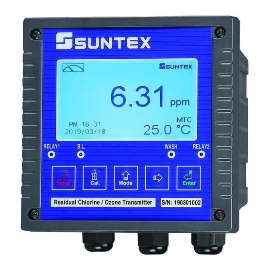
5. Configuration: 5.1 Illustration of front panel: 5.2 Keypad: In order to prevent inappropriate operation by others, before the parameter setting and calibration, the operation applies composite keys and coding protection if necessary. Description of the key functions is in the following: In the parameter set-up mode, pressing this key allows you exit parameter set-up mode and back to Measurement mode. -
Page 19: Led Indicators
+ + : Restore factory default settings + In the Measurement mode, press the two keys 键 simultaneously for five seconds, and then press until you see a clock signal appearing on the display; Then loose all keys to restore factory default settings. -
Page 20: Operation
Low point alarm: AUTO,SP2 =04.00 pH,db2= 0.10 pH Wash time: ON =0000 s.,OFF =000.0 H,db= 0000 s. pH/ORP current output: 4~20 mA,02.00~12.00pH TP current output: 4~20 mA,000.0~100.0 ℃(for PC-3100 only) Display backlit: AUTO,b.L.= 0,SEnS =0 Code set-up: off The followings are for PC-3100RS only: Date and time: 2000-1-1 0Hr 0Minute 0sencond RS-485 set-up: ID= 31,baud speed= 9600... -
Page 21: Settings
7. Settings Block diagram of settings: Password Input Enter Upwards is required set-up code PC-3100RS only PC-3100 mode Downwards only :ENTER Relay1 Relay2 pH/ORP ℃ b.L. Temp SERL Conf Code No code (high point ) (Temperatu Cleaning output (Backlit output... -
Page 22: Entry Of Set-Up Mode
7.1 Entry of set-up mode In the measurement mode, pressing the two keys simultaneously + allows you enter the parameter set-up mode. You can back to the measurement mode at any time by pressing the key . The original code is 1111. 7.2 Security code of settings: In the set-up mode, you can set up the code by pressing the key , and confirm by... -
Page 23: Measurement Parameters
7.3 Measurement parameters: Enter the measurement parameter set-up Press Press or Select pH or ORP Press Enter temperature parameter setting... -
Page 24: Temperature
7.4 Temperature parameter Enter temperature parameter set-up Press press or press for selection for selection Use standard If necessary, compare If necessary, compare thermometer to test the with the actual with the actual actual temperature of temperature value temperature value the solution, and press tested by standard tested by standard... -
Page 25: Hi Point
7.5 Hi point: Set the TH (THRESHOLD) and DB (DEADBAND) of Hi (REL1). The range for TH is -2.00~16.00pH/-1999~1999mv; while the range for DB is .00~2.00pH/0~200mv. Press Press decide to start up REL1 or not. Press Press set the required alarm Press Press set an appropriate... -
Page 26: Lo Point
7.6 Lo point: Set the TH (THRESHOLD) and DB (DEADBAND) of Lo (REL2). The range for TH is -2.00~16.00pH/-1999~1999mv; while the range for DB is .00~2.00pH/0~200mv. Press Press decide to start up REL2 or not. Press Press set the required alarm Press Press set an appropriate... -
Page 27: Wash Time
7.7 Wash time: Set the automatic starting time and turnoff time of the washing function. If any value is set to be 0, the instrument will automatically stop this function. Press Press to set the starting of the washing function; unit: second Press Press to set the... -
Page 28: Analog Output 1 (Ph/Orp)
7.8 Analog output 1 (pH/ORP): The user can adjust the relative relationship between the pH /ORP measurement range and the output current according to actual situation, in order to improve the recognition of current output. Press for confirmation Press select current output mode 0-20 or 4-20 Press Press... -
Page 29: Analog Output 2 (Temperature) (Pc-3100 Only)
Note: The setting in 7.9 is for PC-3100 only. 7.9 Analog output 2 (temperature) (PC-3100 only) The user can adjust the relative relationship between the TEMP measurement range and the output current according to actual situation, in order to improve the recognition of current output. -
Page 30: Time And Date Setting (Pc-3100Rs Only)
Note: The setting in 7.10 and 7.11 is for model PC-3100RS only. 7.11 RS-485 set-up (PC-3100RS only) 7.10 Date and Time setting The user can set, as necessry, the ID and transmission speed of the series output interface. Press Press Press to set the year... -
Page 31: Backlit Lcd
7.12 Backlit LCD to select Press for confirmation to select automatic, manual or off. automatic, manual or off. Press for confirmation Press for confirmation select -2, -1,0,1,2 five select -2, -1,0,1,2 five backlit brightness levels backlit brightness levels Press Press Press for confirmation select-2,-1,0,1,2 five... -
Page 32: Calibration Block Diagram Of Calibration
8. Calibration Block diagram of Calibration: Input Enter Password external code calibratio n mode OS value of Code rEdy rEdy rEdy last calibration (Manual) (Automatic) (Manual) PASS Show the Identify the Default Identify the calibrated standard Slope value standard Code Set 1111 of last electrical... -
Page 33: Security Code Of Calibration
8.1 Security code of calibration: 8.1.1Code authorization: The code authorization of parameter set-up is prior to the code authorization of calibration mode. Therefore, in order to enter the calibration model, you can input the parameter set-up model or the code of calibration mode. -
Page 34: Entry Of Calibration Mode
8.2 Entry of calibration mode 8.2.1 Pressing simultaneously allows entering calibration mode, + and pressing at any time allows backing to the measurement mode. 8.2.2 In entering the calibration mode, the display shows the previous calibration OS (null-point potential) value. Pressing allow entering the next page. -
Page 35: Asymmetry Buffer Calibration
8.3 Asymmetry Buffer calibration 8.3.1 Single-point calibration: In single-point calibration, it is only necessary to calibrate OS value and the unmodified SLP value. The instrument will apply the factory defaults or the SLP value of last calibration. 1. When entering CA1 calibration mode, clean the electrode with distill water before putting it in the buffer solution. -
Page 36: Standard Buffer Calibration
When entering CA2 calibration mode, clean the electrode with distill water before putting it in the buffer solution. Press to start the calibration. Then display will show the mV value of the buffer and begin to twinkle. After showing a similar number of pH value to the buffer solution, push to set the digit until it is equal to the buffer’s standard. - Page 37 4. The display will show mV value while being calibrated. After the value becomes stable, the display will show the second pH value of calibration. Then, it will enter the calibration mode. 5. When being calibrated successfully, it will show “CAL PASS”.
- Page 38 4. The display will show mV value while being calibrated. After the value becomes stable, the display will show the second pH value of calibration. Then, it will enter the third calibration (Ct3). 5. Clean the electrode completely, and put it into the second buffer solution.
-
Page 39: Orp Calibration
8.5 ORP calibration: It is unnecessary to make regular calibration for ORP electrode as pH electrode, and it is only necessary to use ORP Buffer to check the electrode or adjust the deviation of electrical potential. Push for the adjustment of ORP +... -
Page 40: Illustration Of Connection For Rs-485
9.1 Illustration of connection for RS-485 <Important!> No matter how many controllers are used for RS-485 transmission, the last one should be connected to a terminal resistance (so does single controller), so it is necessary to connect a terminal resistance of 100Ω between D+(B) and D-(A) of PC-3100RS. -
Page 41: Instruction Set Of Measurement Mode
「Respond to the input characters (E)」,「Add LF at the end of each input line (A)」 and 「newline if exceeding the width of terminal (W)」, and then leave “ASCII setting” window by pushing 【confirm】. 9. Push 【confirm】to leave “XXX content” window. 10. -
Page 42: Instruction Set Of Set-Up Mode
9.3 RS-485 Instruction set of set-up mode: Instruction format: ABBCC[(XXXX)] [(XXXX)] [(XXXX)] : Instruction leader character : RS-485 ID : Instruction : Omission if there is no parameter (XXXX): Parameter input Readout of parameter settings in set-up mode Syntactic Data feedback Items Instruction function Output format... - Page 43 Input of parameter settings in set-up mode Items Instruction function Instruction language Set the parameter range xxxx: 2000~2099 year Input the date &01SD(xxxx)(yy)(zz) yy : 1~12 month : 1~31 day xx: 0~23 hour Input the time &01ST(xx)(yy)(zz) yy: 0~59 minute zz: 0-59 second Relay1 terminal test &01SH(x)
- Page 44 Note: 1. (xxxx) stands for low current output setting value; (yyyy) stands for high current output setting value. pH mode: setting range -2.00~16.00 pH; for example, 5.00 pH is set as (500) ORP mode: setting range -1999~1999 mV; for example, -250 mV is set as (-250) 2.
-
Page 45: Error Messages (Error Code)
10. Error messages (Error code) Phenomenon Possible cause Dispositions equipment failure Please inform the maintainers for disposition 1. During the 1. Please adjust the buffer calibration, the temperature to the buffer is over appropriate temperature 5~50℃ range and make another 2. -
Page 46: Maintenance
11. Maintenance Generally speaking, if normally operate, the controller produced by our company need no maintenance expect regular cleaning and calibration of the electrode, in order to ensure accurate and stable measurement value and normal system operation. The cleaning cycle for the electrode depends on the pollution degree of the tested water sample.
Need help?
Do you have a question about the PC-3100 and is the answer not in the manual?
Questions and answers