Table of Contents
Advertisement
Quick Links
Air Monitor Corporation
116-047-20.PMD (5/5/11)
Installation, Operation,
and Maintenance Manual
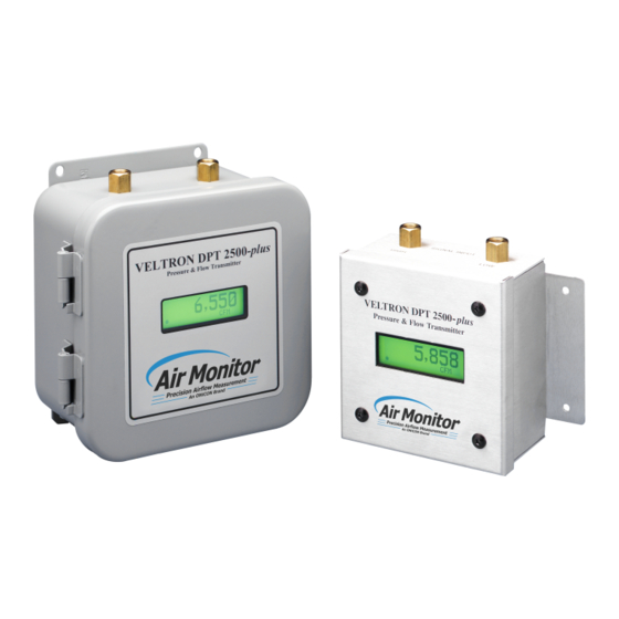
VELTRON DPT 2500-plus
Microprocessor Based Ultra-Low Range
Pressure & Flow "Smart" Transmitter
Version 1.0X
Installation, Operation & Maintenance
Air Monitor Corporation provides complete
technical support between the hours of
7 a.m. and 5 p.m. PST, M-F
Contact our Service Department
Toll Free: 1-800-AIRFLOW
or fax us at 1-707-526-2825
VELTRON DPT 2500-plus
- IO&M Manual
Advertisement
Table of Contents

Related Manuals for Air Monitor VELTRON DPT 2500-plus

Summary of Contents for Air Monitor VELTRON DPT 2500-plus
- Page 1 Microprocessor Based Ultra-Low Range Pressure & Flow "Smart" Transmitter Version 1.0X Installation, Operation & Maintenance Air Monitor Corporation provides complete technical support between the hours of 7 a.m. and 5 p.m. PST, M-F Contact our Service Department Toll Free: 1-800-AIRFLOW...
-
Page 3: Table Of Contents
TABLE OF CONTENTS VELTRON DPT 2500-plus TABLE OF CONTENTS INSTRUMENT WARRANTY ........................i SECTION 1 – GENERAL INFORMATION DESCRIPTION ..........................1 THEORY OF OPERATION ......................1 SECTION 2 – PERFORMANCE SPECIFICATIONS TRANSMITTER ..........................2 INDICATION ........................... 2 OUTPUTS ............................2 POWER ............................ - Page 4 TABLE OF CONTENTS VELTRON DPT 2500-plus TABLE OF CONTENTS SECTION 6 – CALIBRATION REQUIRED EQUIPMENT ......................22 PREPARATION ..........................22 TRANSMITTER INPUT CALIBRATION ................... 23-25 TRANSMITTER OUTPUT CALIBRATION ................26-27 SECTION 7 – MAINTENANCE ......................28 SECTION 8 – TROUBLESHOOTING ....................29 SECTION 9 –...
-
Page 5: Instrument Warranty
This document contains confidential technical data, including trade secrets and propriet ary information which are the sole property of Air Monitor Corporation. The use of said data is solely limited to use as specified herein. Any other use is strictly prohibited without the prior written consent of Air Monitor Corporation. -
Page 6: Section 1 - General Information
1 – GENERAL INFORMATION 1.1 – DESCRIPTION The VELTRON DPT 2500-plus is an ultra-low differential pressure "smart" transmitter designed to convert the low magnitude pressure signals generated by airflow stations and probes, or static pressure sensors into an output signal (4-20mA, 0-5VDC or 0-10VDC) linear to pressure or flow. -
Page 7: Section 2 - Performance Specifications
VELTRON DPT 2500-plus SECTION 2 – PERFORMANCE SPECIFICATIONS 2 – PERFORMANCE SPECIFICATIONS 2.1 – TRANSMITTER 2.2 – INDICATION Accuracy. 0.25% of Natural Span, including hysteresis, Display. A backlit, graphical LCD providing single line of deadband, non-linearity, and non-repeatability. data display. Also used for programming. -
Page 8: Section 3 - Features
3.5 – HIGH TURNDOWN RATIO OPERATION The VELTRON DPT 2500-plus transmitter, with its high level of accuracy and automatic zeroing circuitry, can maintain linear output signals on applications requiring velocity turndown of 10 to 1 (equal to a velocity pressure turndown of 100 to 1). -
Page 9: Section 4 - Installation
• Carefully remove the VELTRON DPT 2500-plus from the shipping container and inspect for any damage. If any damage has occurred in transit, contact freight carrier. • Save the shipping cont ainer for possible future use in returning the VELTRON DPT 2500-plus to the factory for recalibration. -
Page 10: Mounting
– Tools Required: Electric drill; #25 (0.1495") bit; screwdriver or nutdriver; and four #8-32 self-tapping machine screws. – The VELTRON DPT 2500-plus can be mounted in any position provided it is secured using all four mounting holes. – Reasonable consideration should be given to clearances for pressure and electrical connections. -
Page 11: Process Connections
To these connect the appropriate fittings for the type and size of signal tubing used. Although any size tubing can be used, the response time of the VELTRON DPT 2500-plus to process change can increase if there is an increase in tubing size or an increase in tube length. -
Page 12: Power/Signal Connections
4.5 – POWER/SIGNAL CONNECTIONS All wiring is done at the terminal strip of the VELTRON DPT 2500-plus. The cover needs to be opened or removed to gain access to the terminal strip. On the industrial version, the signal/power wires need to be routed through the conduit connection on the bottom side of the enclosure. -
Page 13: Section 5 - Operation
VELTRON DPT 2500- plus Factory Information Set-Up Sheet, provided with the unit. Review this information and verify that the VELTRON DPT 2500-plus set-up is correct for your application. If any problems or discrep ancies are detected, contact Air Monitor's Customer Service Department at 1-800-AIRFLOW prior to proceeding. -
Page 14: Normal Operation
VELTRON DPT 2500-plus SECTION 5 – OPERATION 5.3 – NORMAL OPERATION Under Normal operation the VELTRON DPT 2500-plus display will continuously indicate the current monitored process variable, as the example below shows. 10,000 AUTO-zero. At periodical intervals* (see Factory Set-Up Information Sheet) the AUTO-zero cycle will be initiated. -
Page 15: Pushbutton Definition
VELTRON DPT 2500-plus SECTION 5 – OPERATION 5.5 – PUSHBUTTON DEFINITION The four pushbuttons used to interface with the VELTRON DPT 2500-plus are identified by their symbols. The symbols are defined as follows: DOWN ENTER ESCAPE In addition to Configuration programming, pushbuttons can be used for certain functions when in the Normal operation mode. -
Page 16: Configuration Programming
VELTRON DPT 2500-plus SECTION 5 – OPERATION 5.6 – CONFIGURATION PROGRAMMING With power ON and initialization complete (see Section 5.2), press and display will indicate: USER SETUP Pressing will enter the user into the Main Menu of configuration programming. The display will indicate:... - Page 17 VELTRON DPT 2500-plus SECTION 5 – OPERATION 5.6 – CONFIGURATION PROGRAMMING (con't) Once the desired Selection is displayed, its sub-menu can be entered by pressing To better understand the process of Configuration Programming, arrows with pushbutton designations have been included on the following flow chart of AUTO-zero Configuration. This will aid in the navigation of the Configuration Programming Process.
-
Page 18: Transmitter Scaling & Configuration
SECTION 5 – OPERATION 5.7 – TRANSMITTER SCALING & CONFIGURATION This Main Menu selection is where all application specific data is entered to configure the VELTRON DPT 2500-plus for a unique application. Typical data includes: Process Type, Process Units, Process Minimum/Maximum, and Output Lockdown. - Page 19 VELTRON DPT 2500-plus SECTION 5 – OPERATION 5.7 – TRANSMITTER SCALING & CONFIGURATION (con't) 1. While in Main Menu, use to scroll to: Transmitter Scaling and Configuration 2. Press to enter Transmitter Scaling & Configuration menu. Display will indicate: Square Root On/Of f Configuration 3.
- Page 20 VELTRON DPT 2500-plus SECTION 5 – OPERATION 5.7 – TRANSMITTER SCALING & CONFIGURATION (con't) UNITS LIST for Process Type – Flow UNIT OF MEASUREMENT DISPLAY cubic feet per second cubic feet per minute cubic feet per hour liters per second...
- Page 21 VELTRON DPT 2500-plus SECTION 5 – OPERATION 5.7 – TRANSMITTER SCALING & CONFIGURATION (con't) UNITS LIST for Process Type – Velocity UNIT OF MEASUREMENT DISPLAY feet per second feet per minute feet per hour meters per second meters per minute...
- Page 22 VELTRON DPT 2500-plus SECTION 5 – OPERATION 5.7 – TRANSMITTER SCALING & CONFIGURATION (con't) UNITS LIST for Process Type – Differential Pressure UNIT OF MEASUREMENT DISPLAY inches of water column in.WC inches of mercury in.Hg pounds per square inch, gauge...
-
Page 23: Low Pass Filter
VELTRON DPT 2500-plus SECTION 5 – OPERATION 5.8 – LOW PASS FILTER User can select level of Process filtering applied to the transducer output*. Levels are 0 to 10, with 0 representing no filtering, 1 representing minimal filtering (0.125 sec time constant), and 10 representing maximum filtering (64 sec time constant). -
Page 24: Auto-Zero Configuration
VELTRON DPT 2500-plus SECTION 5 – OPERATION 5.9 – AUTO-zero CONFIGURATION User can turn AUTO-zero function ON or OFF, and select activation interval. User Setup Main Menu Default selection shown. Auto-Zero Configuration Available selections: Available selections: - Auto-Zero Off/On Selection... -
Page 25: Transducer Span Selection
VELTRON DPT 2500-plus SECTION 5 – OPERATION 5.10 – TRANSDUCER SPAN SELECTION Displays the natural span (maximum full scale span) of the transducer installed in the VEL TRON DPT 2500-plus. The displayed natural span is for user/technician reference only and should not be changed unless a new transducer of differential natural span has been installed. -
Page 26: Transmitter Input Calibration
VELTRON DPT 2500-plus SECTION 5 – OPERATION 5.11 – TRANSMITTER INPUT CALIBRATION See Section 6.3 – Calibration for details on Transmitter Input Calibration. User Setup Main Menu Transmitter Input Calib. - Input Zero Calibration - Transducer Span Selection See Calibration - Intput Span Calibration ... -
Page 27: Section 6 - Calibration
This section can be accomplished with the VELTRON DPT 2500-plus mounted in its operating location or at a test bench in a calibration lab. If calibrated at a test bench, the VELTRON DPT 2500-plus should be positioned in the same attitude as in its operat- ing location. -
Page 28: Transmitter Input Calibration
For Units With Positive or Negative Differential Pressure Spans. Zero pressure and transducer natural span pressure will be applied to the VELTRON DPT 2500-plus, unit will be programmed to recognize these pressures as zero and span for transmitter input calibration. - Page 29 5. Slide switch S1 - "AZ Valve" to the OFF position. 6. Apply input pressure (as read on manometer) to the Low Port of the VELTRON DPT 2500-plus. Adjust pressure to equal the positive equivalent of the minimum (negative) transducer natural span value (see Factory Set-Up Information Sheet for this value).
- Page 30 VELTRON DPT 2500-plus SECTION 6 – CALIBRATION 6.3 – TRANSMITTER INPUT CALIBRATION (con't) 6.3.2 (con't) 13. Remove input pressure from High port on VELTRON DPT 2500-plus. 14. Press and then , display will indicate: Return to MAIN MENU 15. Press , and display will be in Main Menu.
-
Page 31: Transmitter Output Calibration
4. Connect a DMM set for the type of output your unit is configured for . DMM should be reading minimum value of (4.00 ± 0.01mA or 0 ± 0.01VDC). 5. If DMM is reading out of tolerance, use to adjust VELTRON DPT 2500-plus output for an acceptable DMM reading. Depending on DMM's selected range the button may need to be pressed and held for a period of time before any change occurs in the DMM's display. - Page 32 Return to MAIN MENU 11. Press and scroll Main Menu to: EXIT User Setup 12. Press and VELTRON DPT 2500-plus will return to Normal mode of operation. Air Monitor Corporation VELTRON DPT 2500-plus - IO&M Manual 116-047-20.PMD (5/5/11)
-
Page 33: Section 7 - Maintenance
Operating experience should be used to set frequency of specific types of maintenance. 7.1 – CLEANLINESS – Verify condensation (or other sources of liquids) are not present inside the VELTRON DPT 2500-plus. 7.2 – MECHANICAL – Verify pressure signal connections are secure. -
Page 34: Section 8 - Troubleshooting
– Verify pressure signal line bulkhead fittings on the transmitter housing have not been spun causing internal signal tubing to twist. If after following the Troubleshooting steps the VELTRON DPT 2500-plus continues to operate improperly, contact the Service Department for further assistance (see Section 10). -
Page 35: Section 9 - Parts List
SECTION 8 – TROUBLESHOOTING 9 – PARTS LIST • The following drawing with part numbers list components of the VELTRON DPT 2500-plus that are easily replaced by the user. • To inquire about price and availability of a specific part number, please contact the Customer Service... -
Page 36: Section 10 - Customer Service
Confirmation of Return Authorization with shipping instructions will be sent via facsimile. Equipment to be returned to Air Monitor should be returned in its original shipping container if possible. If this is not possible, ensure equipment is packaged sufficiently to protect it during shipment.
Need help?
Do you have a question about the VELTRON DPT 2500-plus and is the answer not in the manual?
Questions and answers