
Subscribe to Our Youtube Channel
Summary of Contents for natus Aurical HIT
- Page 1 Aurical HIT and the Otosuite HIT Module User Guide Doc. No. 7-50-1230-EN/07 Part No. 7-50-12300-EN...
- Page 2 Copyright notice © 2012, 2021 Natus Medical Denmark ApS. All rights reserved. ® Natus, the Natus Icon, Otometrics, the Otometrics Icon, Aurical, Madsen, HI-PRO 2, Otoscan, ICS and HORTMANN are registered trademarks of Natus Medical Denmark ApS in the U.S.A. and/or other countries. Version release date...
-
Page 3: Table Of Contents
Table of Contents Introduction Unpacking Installation The test chamber Testing hearing instruments Maintenance and Calibration Other references Technical specifications Definition of symbols 10 Warnings, Cautions, and Notes 11 Manufacturer Aurical HIT... -
Page 4: Introduction
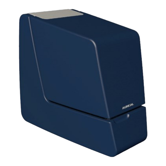
1 Introduction Introduction Aurical® HIT is designed for Hearing Instrument Testing and Coupler-Based Fitting. Aurical® HIT connects via USB to a computer running the Otosuite software. • With the Otosuite HIT Module you can perform traditional hearing instrument testing according to either the ANSI or IEC test protocols, and obtain a con- sistent picture of hearing instruments of each type. -
Page 5: Unpacking
2 Unpacking Unpacking 1. Unpack the device carefully. When you unpack the device and accessories, keep the packing material in which they were delivered. If you need to send the device in for service, the original packing material will protect against damage during transport. 2. - Page 6 4 The test chamber The coupler assembly ► Elevation plate ► Cable groove ► The Aurical® HIT handle ► (some models only) The coupler assembly The coupler assembly consists of the following parts: A. Coupler adapter B. Coupler cavity C. Coupler microphone Aurical HIT...
- Page 7 4 The test chamber Coupler adapter The Accessory Box provides a range of adapters for easy positioning of different types of hearing instruments. Coupler cavity During tests in the test chamber, the hearing instrument is connected to a 2cc coupler cavity manufactured in accordance with the ANSI standard.
-
Page 8: Testing Hearing Instruments
5 Testing hearing instruments Cable groove Wrap the programming cable of the hearing instrument once around the cable groove. This prevents the hearing instrument from being pulled out of place when you close the lid for testing. Elevation plate Use the elevation plate to facilitate positioning of wireless transmitters and body worn hearing instruments at a level where the microphone or microphones are approximately centered in relation to the loudspeaker. - Page 9 5 Testing hearing instruments Calibrating the reference microphone Natus recommends that you calibrate the reference microphone daily or weekly. Set up the interval to suit your purposes. Calibrating the reference microphone ► Positioning the hearing instrument General instructions are described in •...
- Page 10 5 Testing hearing instruments 3. Position the reference microphone (1) pointing straight down from above and centered 1-2 millimeters above the coupler meas- urement microphone (3). 4. During calibration the microphones must have the exact same dis- tance to the main loudspeaker (2), along the Z axis. You can ensure this by looking at the test chamber from the side when you adjust the reference microphone position for calibration.
- Page 11 5 Testing hearing instruments With Aurical® HIT you receive a set of color-coded battery simulators, which are used to power the hearing instru- ment. They are also used as probes for measuring the power consumption. Color code Size ANSI PR63 7012ZD Yellow PR70 7005ZD...
- Page 12 5 Testing hearing instruments Traditional BTE hearing instruments This procedure applies to any type of standard BTE hearing instruments with traditional earmolds. Using the HA-2 adapter and BTE adapter tube Aurical HIT...
- Page 13 5 Testing hearing instruments Thin-tube hearing instruments This type of procedure applies to any type of thin-tube hearing instruments, including instruments with the Receiver In the Ear (RIE)/Receiver In the Canal (RIC), and pre-bent tubing. Using the HA-1 ITE adapter If you place some acoustic putty on the receiver wire this will shift its resonance frequency.
- Page 14 5 Testing hearing instruments ITE hearing instruments This procedure applies to any type of custom hearing instruments, including ITE (In The Ear), ITC (In The Canal), CIC (Com- pletely In the Canal). Using the HA-1 ITE adapter Telecoil testing 1. Position the hearing instrument in Aurical® HIT as described in Traditional BTE hearing instruments ►...
- Page 15 5 Testing hearing instruments For a detailed description of traditional FM testing, see the Aurical® HIT Reference Manual. 5.10 How to perform a standard test The procedure 1. Launch the fitting software for the hearing instrument so that you can control its parameters. Navigation 2.
-
Page 16: Maintenance And Calibration
6 Maintenance and Calibration 5.11 How to test the directional microphone Directionality measurements as described in the hearing instrument test standards cannot be performed with regular desk- top test chambers such as Aurical® HIT. Such measurements require large anechoic chambers. Small test chambers always exhibit acoustic reflections that obscure the true directional behavior of the hearing instrument. -
Page 17: Other References
For Otosuite installation instructions, see the Otosuite Installation Guide, on the Otosuite installation medium. For more information, see the online Help in Otosuite, which contains detailed reference information about Aurical HIT and the Otosuite modules. Technical specifications Type identification Aurical® HIT is type 1082 from Natus Medical Denmark ApS. Aurical HIT... - Page 18 8 Technical specifications Acoustic stimulus generation In closed test chamber Frequency response, re. 1 kHz, main loud- 125 to 200 Hz: ± 3.0 dB speaker (equalized) 200 to 2000 Hz: ± 1.5 dB 2000 to 5000 Hz: ± 2.5 dB 5000 to 10000 Hz: ±...
- Page 19 8 Technical specifications Weight Weight 6.3 kg (13.9 lb) Transport and storage Temperature: -15ºC to +55ºC (5ºF to 131ºF) Air humidity: 10% to 90%, non-condensing Operating environment Operating environment Indoors Operating temperature range 15 to 35 ºC (59 to 95 ºF) Maximum relative humidity Maximum relative humidity 80% for temperatures up to 31ºC (88 ºF) decreas- ing linearly to 50% relative humidity at 40ºC (104 ºF).
-
Page 20: Definition Of Symbols
9 Definition of symbols Definition of symbols Symbol Standards Standard Title of Sym- Symbol Title as Explanation Reference per Referenced Standard ISO 15223- Medical devices — Manufacturer Indicates the medical device man- 1:2016 Refer- Symbols to be used ufacturer. ence no. 5.1.1 with medical device (ISO 7000- labels, labelling and... - Page 21 9 Definition of symbols ISO 15223- Medical devices — Serial number Indicates the manufacturer's serial 1:2016 Refer- Symbols to be used number so that a specific medical ence no. with medical device device can be identified 5.1.7. (ISO labels, labeling, and 7000-2498) information to be sup- plied –...
- Page 22 9 Definition of symbols ISO 15223- Medical devices — Do not use if pack- Indicates a medical device that 1:2016 Refer- Symbols to be used age is damaged should not be used if the package ence no. with medical device has been damaged or opened and 5.2.8.
- Page 23 9 Definition of symbols ISO 15223- Medical devices — Not made with Indicates a medical device that is 1:2016 Refer- Symbols to be used Natural Rubber not made with dry natural rubber ence no. with medical device Latex or natural rubber latex as a mater- 5.4.5.
-
Page 24: Warnings, Cautions, And Notes
Directive 2012/19/EU. These regulations state that electrical and electronic waste must be separately collected for the proper treatment and recovery to ensure that WEEE is reused or recycled safely. In line with that commitment Natus may pass along the obligation for take back and recycling to the end user, unless other arrangements have been made. - Page 25 10 Warnings, Cautions, and Notes Warning Do not use the instrument in the presence of flammable agents (gases) or in an oxygen-rich envir- • onment. Warning To disconnect the device from • The device should be turned off before any connections are established. the power supply, pull the USB plug out of the PC, or shut down the PC.
- Page 26 10 Warnings, Cautions, and Notes Caution Carry the device by its handle. Do not use your other hand to support the device by the lid as this may • cause the lid to open and pinch your fingers Caution • Aurical HIT is intended for diagnostic and clinical use by audiologists, ENTs, and other trained health care professionals in testing the hearing of their patients.
-
Page 27: Manufacturer
For detailed information about the device and software modules, refer to product documentation. • Note • Follow all general safety information about any other fitting devices used while operating the Aurical® HIT. Note All IFU documentation is available on the Natus website. • Manufacturer Natus Medical Denmark ApS Hoerskaetten 9, 2630 Taastrup Denmark +45 45 75 55 55 www.natus.com... - Page 28 11 Manufacturer Aurical HIT...
Need help?
Do you have a question about the Aurical HIT and is the answer not in the manual?
Questions and answers