Advertisement
Quick Links
Warning: you must initialize your motor module through the IQ Control Center before use
1
Box Contents
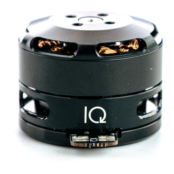
ˆ Motor module
ˆ Power wires
ˆ Communication wires
ˆ Capacitor
ˆ Propeller adapter
ˆ Propeller adapter nut
ˆ Propeller adapter screws
ˆ Mounting screws
ˆ Heat shrink
2
Module Assembly
ˆ Solder power wires to the top part of the PCB
– Black wire to -
– Red wire to +
ˆ Solder communication wires to bottom part of the PCB
– Black wire to -
– Red wire to PCB's TX/Tel
– White wire to PCB's RX/PWM
ˆ Solder external capacitor on top of power wires*
– Cut capacitor leads down to desired size (rec: 8mm)
– Side with white marking to - (over black power wire)
– Side without marking to + (over red power wire)
ˆ Put heat shrink over the wires and capacitor and apply heat
*optional, but suggested when applying more than 8V (2S battery)
2 MODULE ASSEMBLY
Instruction Manual
1/17
V1.1 © 2021 IQinetics Technologies Inc.
Vertiq 2306
Advertisement

Summary of Contents for IQ Vertiq 2306
- Page 1 Vertiq 2306 Instruction Manual Warning: you must initialize your motor module through the IQ Control Center before use Box Contents ˆ Motor module ˆ Power wires ˆ Communication wires ˆ Capacitor ˆ Propeller adapter ˆ Propeller adapter nut ˆ Propeller adapter screws ˆ...
-
Page 2: Module Settings
Vertiq 2306 Module Settings ˆ Download the IQ Control Center (user interface) – Go to www.iq-control.com/support – Click the link provided on the Control Center page. This will direct you to our GitHub page. – Download the Windows .exe file or Mac .dmg file –... - Page 3 Vertiq 2306 Drone Setup ˆ Prior to connecting the modules to your drone, open the IQ Control Center to initialize (see section 3) – Set appropriate module settings using the pre-made settings at the top of the IQ Control Center General tab (see section 11) or set your own –...
- Page 4 – The servo position firmware accepts standard PWM, OneShot, MultiShot, and DShot inputs as well as IQ’s UART protocol and can operate in position, velocity, voltage, or PWM mode – The step/direction firmware mimics a stepper motor with one line as step (TX/Telem), and the other line as the direction (RX/PWM) ˆ...
- Page 5 Vertiq 2306 Connect Computer via USB to UART This is the recommended method for communication. ˆ Connect your FTDI, CP2102, CP2104 or similar device to USB ˆ Using jumper wires connect: – The GND of your USB to UART device to the GND (black) wire on the motor –...
- Page 6 Vertiq 2306 ˆ Connect your Flight Controller (FC) – Plug your FC into your computer through USB – Before you Connect, select your FC’s communication port (check device manager) – Click “Connect” ˆ Making a Backup – Click on the CLI tab in the menu on the left –...
- Page 7 Vertiq 2306 * Now to connect the software serial resources, type: resource Serial_TX 11 resource Serial_RX 11 A10 Tip: the red-colored text above indicates that particular value will change for each motor. So for motor 2, you would type: resource motor 2 none and resource Serial_TX 11 B01. The other two commands remain the same.
- Page 8 ˆ Now you can change settings (see sections 3 and 4) and flash new firmware (see section 12) Tip: the IQ GUI may disconnect or not read a setting from time to time on some older flight controllers because softserial requires a lot of CPU. If this happens, just reconnect the motor and check to make sure you saved all the settings you changed.
- Page 9 Vertiq 2306 ˆ Open your backup file in any text editor ˆ Select all (ctrl-a in Windows) and copy the text (ctrl-c in Windows) ˆ Switch back to the BetaFlight GUI ˆ Click on the CLI tab ˆ In the textbox, paste the copied settings (ctrl-v in Windows), then press enter ˆ...
- Page 10 Vertiq 2306 ˆ Your flight controller will restart. If the GUI doesn’t disconnect automatically, press “Disconnect” You’re done! Get flying! Connect Computer via Arduino Warning: Not Recommended! This method is not reliable for firmware upgrades. There are two styles of Arduino (or similar) boards regarding their USB capabilities: the first are the simple boards that have a USB to UART converter (UNO, etc.) and the second are the boards that have a direct...
- Page 11 Vertiq 2306 Motor connected to Arduino Mega using Method 1 V1.1 © 2021 IQinetics Technologies Inc. 11/17 9 CONNECT COMPUTER VIA ARDUINO...
- Page 12 Serial ports like the Mega. ˆ Connect the Arduino to the USB port of your computer ˆ Load the below sketch on your Arduino (also available in the IQ Arduino examples) // Use this #define to indicate which UART/TTL port to use...
- Page 13 Motor 1 is <index> 0 Motor 2 is <index> 1 Motor 3 is <index> 2 Motor 4 is <index> 3 ˆ The following command values are supported by the IQ motors: 0 <Disarm> 1 <Beep 1> 2 <Beep 2> V1.1 © 2021 IQinetics Technologies Inc.
- Page 14 Vertiq 2306 3 <Beep 3> 4 <Beep 4> 5 <Beep 5> 7 <Spin direction CCW> 8 <Spin direction CW> 9 <3D mode off> 10 <3D mode on> 12 <Save direction and 3D mode> ˆ For example, if you want to change Motor 3 to CW 3D, type the following in the CLI:...
-
Page 15: Flashing New Firmware
– position factory default - factory default, unconfigured ˆ Make your own pre-settings (for advanced users) – Locate and open the IQ Control Center’s “resources” folder – Open the “defaults” folder – Here you will see all of the .json files that correspond to the GUI’s pre-made settings list –... -
Page 16: Safety Instructions
Safety Instructions ˆ IQ motor modules and the machines they actuate can be dangerous and cause bodily harm. Please use caution when working with motors. -
Page 17: Revision History
Table 1: Revision History Version Date Changes 2019-03-07 Initial Version 2021-04-14 Added recommended communication type and reordered based on reliability. Changed hyperlinks. Updated Flashing New Firmware to reflect IQ Control Cen- ter improvements. V1.1 © 2021 IQinetics Technologies Inc. 17/17 14 REVISION HISTORY...
Need help?
Do you have a question about the Vertiq 2306 and is the answer not in the manual?
Questions and answers