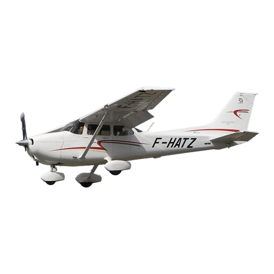
Cessna 172 Maintenance Manual

Cessna 172 Maintenance Manual

Single engine models
Hide thumbs Also See for 172:

Advertisement

Maintenance Manual
SINGLE ENGINE
MODELS 172, 182,
T182, 206 AND T206
1996 And On
.
Member of GAMA
COPYRIGHT © 1996
2 DECEMBER 1996
CESSNA AIRCRAFT COMPANY
WICHITA, KANSAS, USA
REVISION 4
1 JUNE 2005
SESR04

Advertisement

Table of Contents
loading
Need help?

Need help?

Do you have a question about the 172 and is the answer not in the manual?

Questions and answers

Frank
February 13, 2025

Which mannual shows the R&R for the Nose Gear Strut seals for a C-172A

1 comments:
Mr. Anderson
May 14, 2025

The "Cessna Aircraft Company Single Engine Structural Repair Manual" is the manual that would show the removal and replacement for the nose gear strut seals for a Cessna 172.

This answer is automatically generated

Frank
February 10, 2025

parts break down of Nose Gear Strut for C-172A for seals replacement

1 comments:
Frank
February 13, 2025

Which mannual shows removal and replacement of the seals for the C-172A Nose Gear Strut?

Summary of Contents for Cessna 172

  • Page 1 Maintenance Manual SINGLE ENGINE MODELS 172, 182, T182, 206 AND T206 1996 And On Member of GAMA COPYRIGHT © 1996 2 DECEMBER 1996 CESSNA AIRCRAFT COMPANY WICHITA, KANSAS, USA REVISION 4 1 JUNE 2005 SESR04...
  • Page 2 00-Record of Temporary Revisions 00-Table of Contents INTRODUCTION Pages 1-3 Jun 1/2005 LIST OF REVISIONS Page 1 Jun 1/2005 LIST OF CHAPTER Page 1 Jun 1/2005 00 - LIST OF EFFECTIVE PAGES Page 1 of 1 © Cessna Aircraft Company Jun 1/2005...
  • Page 3 Removed Number Number Inserted Removed Number <!DOCTYPE chapter-toc PUBLIC "-//Cessna D171G031//DTD MM Generic V1.0//EN"><chapter-toc chapnbr="" model=""> </chapter-toc><!DOCTYPE chapter-lot PUBLIC "-//Cessna D171G031//DTD MM Generic V1.0//EN"> <chapter-lot> <table> <tgroup cols="3"> <colspec colnum="1" colwidth="3*"> <colspec colnum="2" colwidth="12*"> <colspec colnum="3" colwidth="4*"> <tbody></tbody></tgroup></table></chapter-lot> Page 01...
  • Page 4 CESSNA AIRCRAFT COMPANY MAINTENANCE MANUAL RECORD OF TEMPORARY REVISIONS Temporary Revision Page Number Issue Date Date Removed Number...
  • Page 5: Table Of Contents

    LIST OF CHAPTERS............. LIST OF CHAPTERS Page 1 CONTENTS Page 1 of 1 © Cessna Aircraft Company Jun 1/2005...
  • Page 6: Introduction

    Coverage The Cessna Single Engine Structural Repair Manual is prepared in accordance with the Air Transport Association Specification 2200 for Manufacturers’ Technical Data. This Structural Repair Manual contains material identification for structure subject to field repair; typical repairs applicable to structural components;...
  • Page 7: Introduction

    Revision, draw a vertical line between the applicable frames which is wide enough to show on the edges of the pages. Temporary Revisions should be collected and maintained in a notebook or binder near the aerofiche library for quick reference. INTRODUCTION Page 2 Jun 1/2005 © Cessna Aircraft Company...
  • Page 8: Introduction

    When extensive technical changes are made to text in an existing section that requires extensive revision, revision bars will appear the full length of text. When art is revised or added, a change bar will appear on the full length of the page. INTRODUCTION Page 3 Jun 1/2005 © Cessna Aircraft Company...
  • Page 9: List Of Revisions

    Table 1. Original Issue--2 December 1996 Revision Number Date Writer Revision Number Date Writer 16 May 1997 16 July 1999 15 January 2001 1 June 2005 LIST OF REVISIONS Page 1 Jun 1/2005 © Cessna Aircraft Company...
  • Page 10: List Of Chapters

    Jun 1/2005 Wings Jun 1/2005 Powerplant Jun 1/2005 NOTE 1: *Represents date of page one of each chapter's List of Effective Pages which is applicable to Manual revision date. LIST OF CHAPTERS Page 1 Jun 1/2005 © Cessna Aircraft Company...
  • Page 11 CHAPTER STANDARD PRACTICES - STRUCTURES...
  • Page 12 Page 801 Jun 1/2005 51-73-00 Pages 801-802 Jun 1/2005 51-73-01 Page 801 Jun 1/2005 51-75-00 Pages 801-808 Jun 1/2005 51-76-00 Pages 801-803 Jun 1/2005 51 - LIST OF EFFECTIVE PAGES Page 1 of 1 © Cessna Aircraft Company Jun 1/2005...
  • Page 13 CESSNA AIRCRAFT COMPANY MAINTENANCE MANUAL RECORD OF TEMPORARY REVISIONS Temporary Revision Page Number Issue Date Date Removed Number...
  • Page 14 Temporary Repairs ............51-73-01 Page 801 CONTENTS Page 1 of 2 © Cessna Aircraft Company Jun 1/2005...
  • Page 15 General ..............51-76-00 Page 801 CONTENTS Page 2 of 2 © Cessna Aircraft Company Jun 1/2005...
  • Page 16 7075-T73 aluminum alloy forgings. Nose gear components are 4130 alloy steel and 7075- T73 aluminum alloy forgings. The engine mount is constructed of welded 4130 steel tubing on the 172 and 182. The 206 has a built-up aluminum sheet metal engine mount.
  • Page 17 Points of attachment should be examined carefully for distortion and security of fastenings in the primary and secondary damaged areas at locations beyond the local 51-10-00 Page 1 Jun 1/2005 © Cessna Aircraft Company...
  • Page 18 Areas of structure which are damaged and then repaired in the field, must be refinished to restore the original paint and corrosion protectant properties to factory standards. Refer to applicable airplane Maintenance Manual, Chapter 20, Exterior Finish - Cleaning/Painting, for refinishing procedures and required materials. 51-10-00 Page 2 Jun 1/2005 © Cessna Aircraft Company...
  • Page 19 The most easily oxidized surface becomes the anode and corrodes. The less active member of the couple becomes the cathode 51-11-00 Page 1 Jun 1/2005 © Cessna Aircraft Company...
  • Page 20 CESSNA AIRCRAFT COMPANY SINGLE ENGINE STRUCTURAL REPAIR MANUAL Corrosion Identification Figure 1 (Sheet 1) 51-11-00 Page 2 Jun 1/2005 © Cessna Aircraft Company...
  • Page 21 Stainless Steel control cables. Checking for corrosion on control cables is normally accomplished during the preventative maintenance check. During preventative maintenance, broken wire and wear of the control cable is also checked. 51-11-00 Page 3 Jun 1/2005 © Cessna Aircraft Company...
  • Page 22 If the area is inaccessible, clay impressions, or any other means which will give accurate results, should be used. In the event the corrosion damage is severe or worse, contact Cessna Propeller Aircraft Product Support, P.O. Box 7706, Wichita, KS 67277 USA, for assistance.
  • Page 23 flaking. Pitting depths may be as deep as 15 percent of the material thickness. This type of damage is normally repaired by complete part replacement, but patches or other types of repair may be available. Contact Cessna Propeller Aircraft Product Support, P.O. Box 7706, Wichita, KS 67277 USA, for assistance.
  • Page 24 CESSNA AIRCRAFT COMPANY SINGLE ENGINE STRUCTURAL REPAIR MANUAL Abrasives for Corrosion Removal Figure 2 (Sheet 1) 51-11-00 Page 6 Jun 1/2005 © Cessna Aircraft Company...
  • Page 25 The shotpeen specification is to be Almen intensity of 0.012 to 0.016 using 330 steel shot. After the spring is installed, refinish any damaged or removed finish paint. NOTE: Additional information regarding corrosion control can be found in AC-43-4, Chapter 6, or AC43.13-1B Chapter 6. 51-11-00 Page 7 Jun 1/2005 © Cessna Aircraft Company...
  • Page 26 Make sure the diameter of the axle attachment holes is 0.321 inches maximum for 5/16 inch bolts. If reaming to the maximum dimension does not remove all signs of corrosion, discard the landing gear spring. 51-11-00 Page 8 Jun 1/2005 © Cessna Aircraft Company...
  • Page 27 Illustrated Parts Catalogs do not identify the standard shape from which parts are fabricated. Detailed measurements of damaged areas are required to determine the standard section from which parts are fabricated. 51-30-00 Page 1 Jun 1/2005 © Cessna Aircraft Company...
  • Page 28 CESSNA AIRCRAFT COMPANY SINGLE ENGINE STRUCTURAL REPAIR MANUAL Extrusions and Formed Sections Figure 1 (Sheet 1) 51-30-00 Page 2 Jun 1/2005 © Cessna Aircraft Company...
  • Page 29 CESSNA AIRCRAFT COMPANY SINGLE ENGINE STRUCTURAL REPAIR MANUAL Extrusions and Formed Sections Figure 1 (Sheet 2) 51-30-00 Page 3 Jun 1/2005 © Cessna Aircraft Company...
  • Page 30 CESSNA AIRCRAFT COMPANY SINGLE ENGINE STRUCTURAL REPAIR MANUAL Extrusions and Formed Sections Figure 1 (Sheet 3) 51-30-00 Page 4 Jun 1/2005 © Cessna Aircraft Company...
  • Page 31 CESSNA AIRCRAFT COMPANY SINGLE ENGINE STRUCTURAL REPAIR MANUAL Extrusions and Formed Sections Figure 1 (Sheet 4) 51-30-00 Page 5 Jun 1/2005 © Cessna Aircraft Company...
  • Page 32 NAS1241 repair rivets replace MS20426 rivets if they have the same suffix. NAS1242 repair rivets replace MS20470 rivets if they have the same suffix. 51-40-00 Page 1 Jun 1/2005 © Cessna Aircraft Company...
  • Page 33 While holding the drill at a 90° angle, drill the rivet to the depth of its head. Be careful not to drill too deep because the rivet 51-40-00 Page 2 Jun 1/2005 © Cessna Aircraft Company...
  • Page 34 0.071 NAS1398D6 0.063 NAS1738B6, NAS1738E6, NAS1738D, CR3213-6 MS20426AD3 (Countersunk) 0.063 NAS1398B4, NAS1399D4 (Refer to Note 1) 0.040 NAS1739D4 MS20426AD4 (Countersunk) 0.080 NAS1399B4, NAS1399D4, CR3213-4 0.050 NAS1739D4 MS20426AD4 (Dimpled) 0.063 NAS1739B4, NAS1739E4 51-40-00 Page 3 Jun 1/2005 © Cessna Aircraft Company...
  • Page 35 NAS179, (Refer to Notes 1, NAS14XX NAS1080C, NAS1080E, NAS528 NAS1080G, NAS1080AG (Refer to Notes 1, NAS529 NAS528, NAS179 3, 4) (Refer to Notes 1, NAS1446 NAS1080C, NAS1080E, 2, 5) NAS1080G, NAS1080AG 51-40-00 Page 4 Jun 1/2005 © Cessna Aircraft Company...
  • Page 36 fit each type of rivet. The depth of this set must not touch material being riveted. Parts requiring heat treatment should be heat treated before riveting, since heat 51-40-00 Page 5 Jun 1/2005 © Cessna Aircraft Company...
  • Page 37 CESSNA AIRCRAFT COMPANY SINGLE ENGINE STRUCTURAL REPAIR MANUAL Rivet Removal and Rivet Edge Distance Figure 1 (Sheet 1) 51-40-00 Page 6 Jun 1/2005 © Cessna Aircraft Company...
  • Page 38 In some areas where the spacing between rivets prohibits the use of the next larger rivets, special repair instructions and procedures shall be followed. Contact Cessna Single Engine Support.
  • Page 39 In some instances, it may be necessary to use the next larger size rivet. Loose fasteners may be indicated by the following situation: The fastened material moves relative to the fastener. Skin deflection is evident. 51-40-00 Page 8 Jun 1/2005 © Cessna Aircraft Company...
  • Page 40 CESSNA AIRCRAFT COMPANY SINGLE ENGINE STRUCTURAL REPAIR MANUAL Installation of Blind Rivets Figure 2 (Sheet 1) 51-40-00 Page 9 Jun 1/2005 © Cessna Aircraft Company...
  • Page 41 filling" action built into blind rivets from overloading the non-metal hole. The hole in the washer should match the specified installation hole for the fastener. If the tail end of the rivet is installed through metal substructure, the washer is not necessary. 51-40-00 Page 10 Jun 1/2005 © Cessna Aircraft Company...
  • Page 42 CESSNA AIRCRAFT COMPANY SINGLE ENGINE STRUCTURAL REPAIR MANUAL Red Lining of Fasteners Figure 3 (Sheet 1) 51-40-00 Page 11 Jun 1/2005 © Cessna Aircraft Company...
  • Page 43 If the original equipment rivet provided connection between metal parts as well as non-metallic parts, it may be a standard (AD) rivet. Original equipment AD rivets are colored gold or uncolored. Replace original equipment AD rivets with AD rivets. 51-40-00 Page 12 Jun 1/2005 © Cessna Aircraft Company...
  • Page 44 Proper balance of control surfaces is critical to prevent flutter during normal operating conditions. Tools and Equipment NAME NUMBER MANUFACTURER Control Surface 5180002–1 Cessna Aircraft Co. Cessna Balance elevator and Balance Fixture Kit Part Distribution aileron. 5800 E. Pawnee P.O. Box 1521...
  • Page 45 CESSNA AIRCRAFT COMPANY SINGLE ENGINE STRUCTURAL REPAIR MANUAL Flight Control Surface Balancing Fixture Kit Figure 1 (Sheet 1) 51-60-00 Page 2 Jun 1/2005 © Cessna Aircraft Company...
  • Page 46 CESSNA AIRCRAFT COMPANY SINGLE ENGINE STRUCTURAL REPAIR MANUAL Balancing Control Surfaces Figure 2 (Sheet 1) 51-60-00 Page 3 Jun 1/2005 © Cessna Aircraft Company...
  • Page 47 CESSNA AIRCRAFT COMPANY SINGLE ENGINE STRUCTURAL REPAIR MANUAL Balancing Control Surfaces Figure 2 (Sheet 2) 51-60-00 Page 4 Jun 1/2005 © Cessna Aircraft Company...
  • Page 48 CESSNA AIRCRAFT COMPANY SINGLE ENGINE STRUCTURAL REPAIR MANUAL Balancing Control Surfaces Figure 2 (Sheet 3) 51-60-00 Page 5 Jun 1/2005 © Cessna Aircraft Company...
  • Page 49 CESSNA AIRCRAFT COMPANY SINGLE ENGINE STRUCTURAL REPAIR MANUAL Balancing Control Surfaces Figure 2 (Sheet 4) 51-60-00 Page 6 Jun 1/2005 © Cessna Aircraft Company...
  • Page 50 flight limits must take into account all items which may be attached and/or applied to the various control surfaces (static wicks, trim tabs, paint, decorative trim stripes, and so forth). Table 1. Model 172 Static Balance Limits. CONTROL SURFACE STATIC BALANCE LIMITS APPROVED FOR FLIGHT CONFIGURATION (INCH-LBS).
  • Page 51 Table 3. Model 206 Static Balance Limits. CONTROL SURFACE STATIC BALANCE LIMITS APPROVED FOR FLIGHT CONFIGURATION (INCH-LBS). AILERON 0.0 TO +3.0 RUDDER (Landplane) -4.0 TO +3.0 LEFT ELEVATOR 0.0 TO +12.1 RIGHT ELEVATOR 0.0 TO +12.1 51-60-00 Page 8 Jun 1/2005 © Cessna Aircraft Company...
  • Page 52 The airplane should be located in an area where, once positioned, minimum movement or relocation is required. The airplane should be leveled and supported as necessary. Refer to appropriate Maintenance Manual, Chapter 7, Jacking - Maintenance Practices and Chapter 8, Leveling - Maintenance Practices. 51-70-00 Page 801 Jun 1/2005 © Cessna Aircraft Company...
  • Page 53 Maintenance Manual, Chapter 20, Exterior Finish - Cleaning/Painting for refinishing procedures and required materials. NOTE: Damage adjacent to a previous repair requires removal of the old repair and inclusion of the entire area in the new repair. 51-71-00 Page 801 Jun 1/2005 © Cessna Aircraft Company...
  • Page 54 (10) Smooth patched area with 600-grit sandpaper until desired finish is obtained. (11) Repaint finished area with matching paint. Refer to the applicable Maintenance Manual, Chapter 20, Exterior Finish - Cleaning/Painting for painting procedures. 51-73-00 Page 801 Jun 1/2005 © Cessna Aircraft Company...
  • Page 55 CESSNA AIRCRAFT COMPANY SINGLE ENGINE STRUCTURAL REPAIR MANUAL Typical Glass Fiber Panel Repair Figure 801 (Sheet 1) 51-73-00 Page 802 Jun 1/2005 © Cessna Aircraft Company...
  • Page 56 Cracks in more than 10 percent of the attach fastener locations per fairing. Fairings, with a stop drilled crack that does not extend past the stop drilled hole, may remain in service until the next 100 hour or equivalent inspection. 51-73-01 Page 801 Jun 1/2005 © Cessna Aircraft Company...
  • Page 57 A crack that passes through a trailing edge rivet and does not extend to the trailing NOTE: edge of the skin may be stop drilled at both ends of the crack. 51-75-00 Page 801 Jun 1/2005 © Cessna Aircraft Company...
  • Page 58 CESSNA AIRCRAFT COMPANY SINGLE ENGINE STRUCTURAL REPAIR MANUAL Skin Repair Figure 801 (Sheet 1) 51-75-00 Page 802 Jun 1/2005 © Cessna Aircraft Company...
  • Page 59 CESSNA AIRCRAFT COMPANY SINGLE ENGINE STRUCTURAL REPAIR MANUAL Skin Repair Figure 801 (Sheet 2) 51-75-00 Page 803 Jun 1/2005 © Cessna Aircraft Company...
  • Page 60 CESSNA AIRCRAFT COMPANY SINGLE ENGINE STRUCTURAL REPAIR MANUAL Skin Repair Figure 801 (Sheet 3) 51-75-00 Page 804 Jun 1/2005 © Cessna Aircraft Company...
  • Page 61 CESSNA AIRCRAFT COMPANY SINGLE ENGINE STRUCTURAL REPAIR MANUAL Skin Repair Figure 801 (Sheet 4) 51-75-00 Page 805 Jun 1/2005 © Cessna Aircraft Company...
  • Page 62 CESSNA AIRCRAFT COMPANY SINGLE ENGINE STRUCTURAL REPAIR MANUAL Skin Repair Figure 801 (Sheet 5) 51-75-00 Page 806 Jun 1/2005 © Cessna Aircraft Company...
  • Page 63 CESSNA AIRCRAFT COMPANY SINGLE ENGINE STRUCTURAL REPAIR MANUAL Corrugated Skin Repair Figure 802 (Sheet 1) 51-75-00 Page 807 Jun 1/2005 © Cessna Aircraft Company...
  • Page 64 Affected control surfaces with corrugated skins and having a stop drilled crack that does not extend past the stop drilled hole, may remain in service without additional repair. Refer to Figure 802 as applicable for repair information. 51-75-00 Page 808 Jun 1/2005 © Cessna Aircraft Company...
  • Page 65 Damage which would involve a control surface repair: After the repair is completed, the control surface balance must be checked as described in Flight Control Surface Balancing. Refer to Figures 801 and 802 which illustrate typical control surface repairs. 51-76-00 Page 801 Jun 1/2005 © Cessna Aircraft Company...
  • Page 66 CESSNA AIRCRAFT COMPANY SINGLE ENGINE STRUCTURAL REPAIR MANUAL Typical Control Surface Rib Repair Figure 801 (Sheet 1) 51-76-00 Page 802 Jun 1/2005 © Cessna Aircraft Company...
  • Page 67 CESSNA AIRCRAFT COMPANY SINGLE ENGINE STRUCTURAL REPAIR MANUAL Typical Control Surface Trailing Edge Repair Figure 802 (Sheet 1) 51-76-00 Page 803 Jun 1/2005 © Cessna Aircraft Company...
  • Page 68 CHAPTER DOORS...
  • Page 69 PAGE DATE 52-Title 52-List of Effective Pages 52-Record of Temporary Revisions 52-Table of Contents 52-00-00 Page 1 Jun 1/2005 52-10-00 Page 101 Jun 1/2005 52 - LIST OF EFFECTIVE PAGES Page 1 of 1 © Cessna Aircraft Company Jun 1/2005...
  • Page 70 CESSNA AIRCRAFT COMPANY MAINTENANCE MANUAL RECORD OF TEMPORARY REVISIONS Temporary Revision Page Number Issue Date Date Removed Number...
  • Page 71 Repairable Damage ............52-10-00 Page 101 CONTENTS Page 1 of 1 © Cessna Aircraft Company Jun 1/2005...
  • Page 72 General Chapter 52 describes general repair practices, materials and procedures which are applicable to the doors and door structure. If questions arise concerning approved repairs or for repairs not shown in this section, contact Cessna Propeller Aircraft Product Support. 52-00-00...
  • Page 73 The strength of the bonded seams in doors may be replaced by a single 3/32, 2117-AD rivet per running inch of bond seam. The standard repair procedures outlined in AC43.13-1b are also applicable to bonded doors. 52-10-00 Page 101 Jun 1/2005 © Cessna Aircraft Company...
  • Page 74 CHAPTER FUSELAGE...
  • Page 75 Pages 1-3 Jun 1/2005 53-10-00 Pages 1-2 Jun 1/2005 53-20-00 Pages 801-805 Jun 1/2005 53-30-00 Pages 801-806 Jun 1/2005 53-40-00 Pages 801-803 Jun 1/2005 53 - LIST OF EFFECTIVE PAGES Page 1 of 1 © Cessna Aircraft Company Jun 1/2005...
  • Page 76 CESSNA AIRCRAFT COMPANY MAINTENANCE MANUAL RECORD OF TEMPORARY REVISIONS Temporary Revision Page Number Issue Date Date Removed Number...
  • Page 77 Repairing the Firewall Assembly..........53-40-00 Page 801 CONTENTS Page 1 of 1 © Cessna Aircraft Company Jun 1/2005...
  • Page 78: Fuselage - General

    Fuselage The fuselage is of semimonocoque construction and consists of formed bulkheads, longitudinal stringers, reinforcing channels and skin panels. If questions arise concerning approved repairs or for repairs not shown in this section, contact Cessna Propeller Aircraft Product Support. 53-00-00...
  • Page 79 CESSNA AIRCRAFT COMPANY SINGLE ENGINE STRUCTURAL REPAIR MANUAL Fuselage Stations Figure 1 (Sheet 1) 53-00-00 Page 2 Jun 1/2005 © Cessna Aircraft Company...
  • Page 80 CESSNA AIRCRAFT COMPANY SINGLE ENGINE STRUCTURAL REPAIR MANUAL Fuselage Stations Figure 1 (Sheet 2) 53-00-00 Page 3 Jun 1/2005 © Cessna Aircraft Company...
  • Page 81: Fuselage Damage Classification

    Typical Skin Repairs. Before repairs are attempted, all cracks or deep scratches must be stop-drilled with a No. 30 (0.128 inch) drill and all sharp corners and ragged edges must be trimmed away and deburred. 53-10-00 Page 1 Jun 1/2005 © Cessna Aircraft Company...
  • Page 82: Replacement Damage

    Structural members of a complicated nature that have been distorted or wrenched should be replaced. Seat rails serve as structural parts of the fuselage and must be replaced if damaged. 53-10-00 Page 2 Jun 1/2005 © Cessna Aircraft Company...
  • Page 83: Cabin Bulkhead Repair

    Bulkheads in the damaged area must be checked for alignment. Deformation of bulkhead webs must be checked using a straightedge. Damaged support structure, buckled floorboards and skins, and damaged or questionable forgings must be replaced. 53-20-00 Page 801 Jun 1/2005 © Cessna Aircraft Company...
  • Page 84 CESSNA AIRCRAFT COMPANY SINGLE ENGINE STRUCTURAL REPAIR MANUAL Typical Cabin Bulkhead Repair Figure 801 (Sheet 1) 53-20-00 Page 802 Jun 1/2005 © Cessna Aircraft Company...
  • Page 85 CESSNA AIRCRAFT COMPANY SINGLE ENGINE STRUCTURAL REPAIR MANUAL Typical Cabin Bulkhead Repair Figure 801 (Sheet 2) 53-20-00 Page 803 Jun 1/2005 © Cessna Aircraft Company...
  • Page 86 CESSNA AIRCRAFT COMPANY SINGLE ENGINE STRUCTURAL REPAIR MANUAL Typical Cabin Bulkhead Repair Figure 801 (Sheet 3) 53-20-00 Page 804 Jun 1/2005 © Cessna Aircraft Company...
  • Page 87 CESSNA AIRCRAFT COMPANY SINGLE ENGINE STRUCTURAL REPAIR MANUAL Typical Rib Repair Figure 802 (Sheet 1) 53-20-00 Page 805 Jun 1/2005 © Cessna Aircraft Company...
  • Page 88: Stringer And Channel Repair

    SINGLE ENGINE STRUCTURAL REPAIR MANUAL STRINGER AND CHANNEL REPAIR General Damage to the stringers or channels can be repairable. Refer to Figure 801 for an illustration of typical stringer and channel repairs. 53-30-00 Page 801 Jun 1/2005 © Cessna Aircraft Company...
  • Page 89 CESSNA AIRCRAFT COMPANY SINGLE ENGINE STRUCTURAL REPAIR MANUAL Typical Stringer and Channel Repair Figure 801 (Sheet 1) 53-30-00 Page 802 Jun 1/2005 © Cessna Aircraft Company...
  • Page 90 CESSNA AIRCRAFT COMPANY SINGLE ENGINE STRUCTURAL REPAIR MANUAL Typical Stringer and Channel Repair Figure 801 (Sheet 2) 53-30-00 Page 803 Jun 1/2005 © Cessna Aircraft Company...
  • Page 91 CESSNA AIRCRAFT COMPANY SINGLE ENGINE STRUCTURAL REPAIR MANUAL Typical Stringer and Channel Repair Figure 801 (Sheet 3) 53-30-00 Page 804 Jun 1/2005 © Cessna Aircraft Company...
  • Page 92 CESSNA AIRCRAFT COMPANY SINGLE ENGINE STRUCTURAL REPAIR MANUAL Typical Stringer and Channel Repair Figure 801 (Sheet 4) 53-30-00 Page 805 Jun 1/2005 © Cessna Aircraft Company...
  • Page 93 CESSNA AIRCRAFT COMPANY SINGLE ENGINE STRUCTURAL REPAIR MANUAL Typical Stringer and Channel Repair Figure 801 (Sheet 5) 53-30-00 Page 806 Jun 1/2005 © Cessna Aircraft Company...
  • Page 94: Firewall Repair

    If the sealant is applied with a brush or a brush flow gun, more than one coat of sealant NOTE: will be necessary on very porous material. Sealant should be allowed to air-dry 10 minutes between coats. 53-40-00 Page 801 Jun 1/2005 © Cessna Aircraft Company...
  • Page 95 CESSNA AIRCRAFT COMPANY SINGLE ENGINE STRUCTURAL REPAIR MANUAL Typical Firewall Repair Figure 801 (Sheet 1) 53-40-00 Page 802 Jun 1/2005 © Cessna Aircraft Company...
  • Page 96 CESSNA AIRCRAFT COMPANY SINGLE ENGINE STRUCTURAL REPAIR MANUAL Firewall Angle Repair Figure 802 (Sheet 1) 53-40-00 Page 803 Jun 1/2005 © Cessna Aircraft Company...
  • Page 97 CHAPTER STABILIZERS...
  • Page 98 Page 1 Jun 1/2005 55-10-00 Page 801 Jun 1/2005 55-20-00 Page 801 Jun 1/2005 55-30-00 Page 801 Jun 1/2005 55-40-00 Page 801 Jun 1/2005 55 - LIST OF EFFECTIVE PAGES Page 1 of 1 © Cessna Aircraft Company Jun 1/2005...
  • Page 99 CESSNA AIRCRAFT COMPANY MAINTENANCE MANUAL RECORD OF TEMPORARY REVISIONS Temporary Revision Page Number Issue Date Date Removed Number...
  • Page 100 Replacement Damage............55-40-00 Page 801 CONTENTS Page 1 of 1 © Cessna Aircraft Company Jun 1/2005...
  • Page 101 Skins are riveted to supporting structure with conventional MS20470AD rivets. If questions arise concerning approved repairs or for repairs not shown in this section, contact Cessna Propeller Aircraft Product Support. 55-00-00 Page 1 Jun 1/2005 ©...
  • Page 102 Ribs and spars may be repaired, but replacement is generally preferable. Where damage is extensive, replacement of the entire assembly is recommended. 55-10-00 Page 801 Jun 1/2005 © Cessna Aircraft Company...
  • Page 103 Chapter 51, Flight Control Surface Balancing. Replacement Damage Warped and cracked skin, ribs, and hinge brackets are replaceable items. Where damage is extensive, replacement of the entire assembly is recommended. 55-20-00 Page 801 Jun 1/2005 © Cessna Aircraft Company...
  • Page 104 Ribs and spars may be repaired, but replacement is generally preferable. Where damage is extensive, replacement of the entire assembly is recommended. 55-30-00 Page 801 Jun 1/2005 © Cessna Aircraft Company...
  • Page 105 Assemblies that have been twisted or warped beyond usable limits and parts with extensive corrosion damage are considered replaceable. Small parts which may be easily fabricated from materials available locally should be replaced. 55-40-00 Page 801 Jun 1/2005 © Cessna Aircraft Company...
  • Page 106 CHAPTER WINDOWS...
  • Page 107 PAGE DATE 56-Title 56-List of Effective Pages 56-Record of Temporary Revisions 56-Table of Contents 56-00-00 Page 1 Jun 1/2005 56-10-00 Pages 801-804 Jun 1/2005 56 - LIST OF EFFECTIVE PAGES Page 1 of 1 © Cessna Aircraft Company Jun 1/2005...
  • Page 108 CESSNA AIRCRAFT COMPANY MAINTENANCE MANUAL RECORD OF TEMPORARY REVISIONS Temporary Revision Page Number Issue Date Date Removed Number...
  • Page 109 Cleaning Plastic ............56-10-00 Page 804 CONTENTS Page 1 of 1 © Cessna Aircraft Company Jun 1/2005...
  • Page 110: Windows - General

    On single engine airplanes. These repairs may be utilized without removing components from the airplane. For windshield/window removal or replacement, refer to the various model Maintenance Manuals, Chapter 56 - Windows. 56-00-00 Page 1 Jun 1/2005 © Cessna Aircraft Company...
  • Page 111: Plastic Window Surface Repair

    3 hours. Allow surface to dry 24 to 36 hours before sanding or polishing is attempted. Insert (Plug) Patch The following procedure should be used when preparing a plug patch. Trim hole to a perfect circle or oval and bevel edges slightly. 56-10-00 Page 801 Jun 1/2005 © Cessna Aircraft Company...
  • Page 112 CESSNA AIRCRAFT COMPANY SINGLE ENGINE STRUCTURAL REPAIR MANUAL Typical Windshield and Windows Repair Figure 801 (Sheet 1) 56-10-00 Page 802 Jun 1/2005 © Cessna Aircraft Company...
  • Page 113 CESSNA AIRCRAFT COMPANY SINGLE ENGINE STRUCTURAL REPAIR MANUAL Typical Windshield and Windows Repair Figure 801 (Sheet 2) 56-10-00 Page 803 Jun 1/2005 © Cessna Aircraft Company...
  • Page 114: Minor Scratches

    CAUTION: Do not use gasoline, alcohol, benzene, acetone, carbon tetrachloride, fire extinguisher or deicing fluids, lacquer thinners, or window cleaning sprays because they will soften the plastic and cause crazing. 56-10-00 Page 804 Jun 1/2005 © Cessna Aircraft Company...
  • Page 115 CHAPTER WINGS...
  • Page 116 Pages 801-802 Jun 1/2005 57-26-00 Pages 801-802 Jun 1/2005 57-27-00 Pages 801-802 Jun 1/2005 57-40-00 Page 801 Jun 1/2005 57-50-00 Page 801 Jun 1/2005 57 - LIST OF EFFECTIVE PAGES Page 1 of 1 © Cessna Aircraft Company Jun 1/2005...
  • Page 117 CESSNA AIRCRAFT COMPANY MAINTENANCE MANUAL RECORD OF TEMPORARY REVISIONS Temporary Revision Page Number Issue Date Date Removed Number...
  • Page 118 57-22-00 Page 601 Model 172 Series Wing Twist Check Procedure ....... .
  • Page 119 Wing Strut Damage Classification ..........57-50-00 Page 801 CONTENTS Page 2 of 2 © Cessna Aircraft Company Jun 1/2005...
  • Page 120 Ribs are formed sheet metal, and consist of nose, intermediate and trailing edge assemblies. On the 172 series airplanes, stressed skin is riveted to the rib and spar assemblies to complete the rigid structure. On 182 and 206 series airplanes, the skin is bonded to the leading edge ribs and riveted at other locations.
  • Page 121 SINGLE ENGINE STRUCTURAL REPAIR MANUAL Cut out access hole, using dimension shown. Flex doubler and insert through access hole, and rivet in place. Position cover and secure, using screws as shown. 57-00-00 Page 2 Jun 1/2005 © Cessna Aircraft Company...
  • Page 122 CESSNA AIRCRAFT COMPANY SINGLE ENGINE STRUCTURAL REPAIR MANUAL Wing and Fuselage Support Stands Figure 1 (Sheet 1) 57-00-00 Page 3 Jun 1/2005 © Cessna Aircraft Company...
  • Page 123 CESSNA AIRCRAFT COMPANY SINGLE ENGINE STRUCTURAL REPAIR MANUAL Access Hole Installation Figure 2 (Sheet 1) 57-00-00 Page 4 Jun 1/2005 © Cessna Aircraft Company...
  • Page 124 Damage necessitating Replacement Of Parts: If damage to an auxiliary spar would require a repair which could not be made between adjacent ribs, the auxiliary spar must be replaced. Wing Rib Damage Criteria Negligible damage: None, other than minor scratches or abrasions. 57-10-00 Page 1 Jun 1/2005 © Cessna Aircraft Company...
  • Page 125 - which are not stress wrinkles and do not interfere with internal structure - constitute negligible damage. However, because of the critical nature of the wing leading edge, this cosmetic repair should be completed. 57-10-00 Page 2 Jun 1/2005 © Cessna Aircraft Company...
  • Page 126 Dings that include corrugations are unlikely to be reworkable, but may be repaired by replacing the damaged area. Corrugated skin material is available from Cessna. Special care must be taken to minimize added weight since the surface must be rebalanced after rework.
  • Page 127 Damage Necessitating Replacement Of Parts: Multiple repairs to the same area must not be made, but a larger repair incorporating both repairs may be made. Skins must be replaced if damage extends across more than one rib. 57-10-00 Page 4 Jun 1/2005 © Cessna Aircraft Company...
  • Page 128 The best method of removing sealant is with a chisel-like tool made of hard fiber or plexiglass. Remaining sealant can be removed with aluminum wool. Steel wool or sandpaper must not be used. 57-11-00 Page 801 Jun 1/2005 © Cessna Aircraft Company...
  • Page 129 (18) Any repair that breaks the fuel bay seal will require resealing that bay area, refer to applicable Maintenance Manual, Chapter 28, Fuel Tank Sealing - Maintenance Practices for sealing materials and procedures. 57-11-00 Page 802 Jun 1/2005 © Cessna Aircraft Company...
  • Page 130 Service Kit SK210-56, available from Cessna Parts Distribution, contains Type I Class B-2 and Type VIII Class B-2 (access) sealants with Cessna Parts Distribution, contains Type I Class B-1/2 and Type VIII Class B-12 (access) sealants with the proper quantity of accelerator for each sealant.
  • Page 131 Apply pressure slowly until one-half psi is obtained. Apply a soap solution as required. Allow 15 to 30 minutes for pressure to stabilize. If bay holds for 15 minutes, without pressure loss, bay is acceptable. 57-12-00 Page 802 Jun 1/2005 © Cessna Aircraft Company...
  • Page 132 CESSNA AIRCRAFT COMPANY SINGLE ENGINE STRUCTURAL REPAIR MANUAL (10) Reseal and retest if any leaks are found. 57-12-00 Page 803 Jun 1/2005 © Cessna Aircraft Company...
  • Page 133 Damage to the wing rib can be divided into three major categories and is detailed in Wing Damage Classification. Wing Rib Repair Repairs to the wing rib are illustrated in Figure 801. 57-20-00 Page 801 Jun 1/2005 © Cessna Aircraft Company...
  • Page 134 CESSNA AIRCRAFT COMPANY SINGLE ENGINE STRUCTURAL REPAIR MANUAL Typical Rib Repair Figure 801 (Sheet 1) 57-20-00 Page 802 Jun 1/2005 © Cessna Aircraft Company...
  • Page 135 CESSNA AIRCRAFT COMPANY SINGLE ENGINE STRUCTURAL REPAIR MANUAL Typical Rib Repair Figure 801 (Sheet 2) 57-20-00 Page 803 Jun 1/2005 © Cessna Aircraft Company...
  • Page 136 Damage to the wing spar can be divided into three major categories and is detailed in Wing Damage Classification. Spar Repair Repairs to the wing spar are illustrated in Figure 801. 57-21-00 Page 801 Jun 1/2005 © Cessna Aircraft Company...
  • Page 137 CESSNA AIRCRAFT COMPANY SINGLE ENGINE STRUCTURAL REPAIR MANUAL Wing Spar Repair Figure 801 (Sheet 1) 57-21-00 Page 802 Jun 1/2005 © Cessna Aircraft Company...
  • Page 138 CESSNA AIRCRAFT COMPANY SINGLE ENGINE STRUCTURAL REPAIR MANUAL Wing Spar Repair Figure 801 (Sheet 2) 57-21-00 Page 803 Jun 1/2005 © Cessna Aircraft Company...
  • Page 139 CESSNA AIRCRAFT COMPANY SINGLE ENGINE STRUCTURAL REPAIR MANUAL Wing Spar Repair Figure 801 (Sheet 3) 57-21-00 Page 804 Jun 1/2005 © Cessna Aircraft Company...
  • Page 140 CESSNA AIRCRAFT COMPANY SINGLE ENGINE STRUCTURAL REPAIR MANUAL Wing Spar Repair Figure 801 (Sheet 4) 57-21-00 Page 805 Jun 1/2005 © Cessna Aircraft Company...
  • Page 141 This section applies to the procedures required to perform a wing twist check and is applicable to both wing. If damage has occurred to a wing, it is advisable to check the wing twist (washout). Wing twist (washout) for the Model 172, 182/T182 and 206/T206 airplanes is 3°37’. Tools, Equipment and Materials...
  • Page 142 Secure protractor to bottom of the straightedge. Hold straightedge parallel to wing station and place bolt "A" on mark. Set bubble in protractor to center, and lock protractor to hold this reading. 57-22-00 Page 602 Jun 1/2005 © Cessna Aircraft Company...
  • Page 143 CESSNA AIRCRAFT COMPANY SINGLE ENGINE STRUCTURAL REPAIR MANUAL Measuring Model 172 Series Wing Twist Figure 601 (Sheet 1) 57-22-00 Page 603 Jun 1/2005 © Cessna Aircraft Company...
  • Page 144 CESSNA AIRCRAFT COMPANY SINGLE ENGINE STRUCTURAL REPAIR MANUAL Measuring Model 182 Series Wing Twist Figure 602 (Sheet 1) 57-22-00 Page 604 Jun 1/2005 © Cessna Aircraft Company...
  • Page 145 Check to assure that protractor bubble is still centered. If proper twist is present, the protractor readings will be the same (parallel). Forward or aft bolt may be lowered from wing 0.10 inch (maximum) to attain NOTE: level indication. 57-22-00 Page 605 Jun 1/2005 © Cessna Aircraft Company...
  • Page 146 CESSNA AIRCRAFT COMPANY SINGLE ENGINE STRUCTURAL REPAIR MANUAL Measuring Model 206/T206 Series Wing Twist Figure 603 (Sheet 1) 57-22-00 Page 606 Jun 1/2005 © Cessna Aircraft Company...
  • Page 147 Damage to the wing stringers can be divided into three major categories and is detailed in Wing Damage Classification. Stringer Repair Repairs to wing stringer are similar to repairs to fuselage stringers. Refer to Chapter 52, Stringer and Channel Repair, Figure 801 for repair illustrations. 57-23-00 Page 801 Jun 1/2005 © Cessna Aircraft Company...
  • Page 148 Damage to the auxiliary spar can be divided into three major categories and is detailed in Wing Damage Classification. Auxiliary Spar Repair Repairs to the auxiliary spar are illustrated in Figure 801. 57-24-00 Page 801 Jun 1/2005 © Cessna Aircraft Company...
  • Page 149 CESSNA AIRCRAFT COMPANY SINGLE ENGINE STRUCTURAL REPAIR MANUAL Auxiliary Spar Repair Figure 801 (Sheet 1) 57-24-00 Page 802 Jun 1/2005 © Cessna Aircraft Company...
  • Page 150: Leading Edge Repairs

    Vertical size of patch is limited by ability to install doubler clear of front spar. Lateral size is limited to seven inches across trimmed out area. Number of repairs is limited to one per bay. 57-25-00 Page 801 Jun 1/2005 © Cessna Aircraft Company...
  • Page 151 CESSNA AIRCRAFT COMPANY SINGLE ENGINE STRUCTURAL REPAIR MANUAL Leading Edge Repair Figure 801 (Sheet 1) 57-25-00 Page 802 Jun 1/2005 © Cessna Aircraft Company...
  • Page 152: Bonded Leading Edge Repair

    Damage to the bonded leading edge can be divided into three major categories and is detailed in Wing Damage Classification. Bonded Leading Edge Repair Repairs to the bonded leading edge are illustrated in Figure 801. 57-26-00 Page 801 Jun 1/2005 © Cessna Aircraft Company...
  • Page 153: Bonded Leading Edge Repair

    CESSNA AIRCRAFT COMPANY SINGLE ENGINE STRUCTURAL REPAIR MANUAL Bonded Leading Edge Repair Figure 801 (Sheet 1) 57-26-00 Page 802 Jun 1/2005 © Cessna Aircraft Company...
  • Page 154: Flap Leading Edge Repair

    Damage to the wing flap can be divided into three major categories and is detailed in Wing Damage Classification. Flap Repairs Repairs to the flap leading edge are illustrated in Figure 801. Repairs to the corrugated skin are illustrated in Chapter 51, Typical Skin Repairs, Figure 802. 57-27-00 Page 801 Jun 1/2005 © Cessna Aircraft Company...
  • Page 155 CESSNA AIRCRAFT COMPANY SINGLE ENGINE STRUCTURAL REPAIR MANUAL Flap Leading Edge Repair Figure 801 (Sheet 1) 57-27-00 Page 802 Jun 1/2005 © Cessna Aircraft Company...
  • Page 156: Flaps And Ailerons

    Chapter 51, Control Surface Repair, Figure 802, are typical flap and aileron repairs. Flight control surfaces which have been repaired or replaced must be balanced in accordance with procedures outlined in Chapter 51, Flight Control Surface Balancing. 57-40-00 Page 801 Jun 1/2005 © Cessna Aircraft Company...
  • Page 157: Wing Lift Struts

    7075-T73 bar stock and attached to the strut tubes. Wing Strut Damage Classification Damage to the wing lift strut can be divided into three major categories and is detailed in Wing Damage Classification. 57-50-00 Page 801 Jun 1/2005 © Cessna Aircraft Company...
  • Page 158 CHAPTER POWER PLANT...
  • Page 159 71-List of Effective Pages 71-Record of Temporary Revisions 71-Table of Contents 71-00-00 Page 1 Jun 1/2005 71-10-00 Page 801 Jun 1/2005 71-20-00 Pages 801-804 Jun 1/2005 71 - LIST OF EFFECTIVE PAGES Page 1 of 1 © Cessna Aircraft Company Jun 1/2005...
  • Page 160 CESSNA AIRCRAFT COMPANY MAINTENANCE MANUAL RECORD OF TEMPORARY REVISIONS Temporary Revision Page Number Issue Date Date Removed Number...
  • Page 161 Engine Mount Repairs ............71-20-00 Page 801 CONTENTS Page 1 of 1 © Cessna Aircraft Company Jun 1/2005...
  • Page 162 This chapter covers structural repair to the cowlings (172R, 172S, 182S, 182T and T182T), and structural repair to the welded engine mounts (172R, 172S, 182S, 182T and T182T). For repair information not covered in this manual, contact Cessna Propeller Aircraft Product Support, P.O. Box 7706, Wichita, KS 67277. Telephone(316) 517-5800 or Facsimile (316) 942-9006.
  • Page 163 fit. Small cracks may be stop drilled and dents straightened if they are reinforced on the inner side with a doubler of the same material. Repair of Reinforcement Angles Due to their small size, cowl reinforcement angles should be replaced (rather than repaired) if they become damaged. 71-10-00 Page 801 Jun 1/2005 © Cessna Aircraft Company...
  • Page 164 Engine mounting lugs and engine mount-to-fuselage attach fittings should be replaced, not repaired. For information on damage beyond the scope of these repairs, consult Cessna Propeller Aircraft Product Support, P.O. Box 7706, Wichita, KS 67277 USA, Telephone (316) 517-5800 or Facsimile (316) 942-9006.
  • Page 165 CESSNA AIRCRAFT COMPANY SINGLE ENGINE STRUCTURAL REPAIR MANUAL Typical Engine Mount Repairs Figure 801 (Sheet 1) 71-20-00 Page 802 Jun 1/2005 © Cessna Aircraft Company...
  • Page 166 CESSNA AIRCRAFT COMPANY SINGLE ENGINE STRUCTURAL REPAIR MANUAL Typical Engine Mount Repairs Figure 801 (Sheet 2) 71-20-00 Page 803 Jun 1/2005 © Cessna Aircraft Company...
  • Page 167 CESSNA AIRCRAFT COMPANY SINGLE ENGINE STRUCTURAL REPAIR MANUAL Typical Engine Mount Repairs Figure 801 (Sheet 3) 71-20-00 Page 804 Jun 1/2005 © Cessna Aircraft Company...

This manual is also suitable for:

182T182206T206

Table of Contents

Save PDF