Table of Contents
Advertisement
Quick Links
Advertisement
Chapters
Table of Contents

Summary of Contents for ZETRON 025-9623 D3
- Page 1 Intelligent Radio Interface Module for Motorola iDEN i365 025-9623 D3...
- Page 2 Zetron Products or Zetron Accessories, or refund the purchase price, at Zetron’s option, after return of such items by buyer to Zetron. Shipment shall be paid for by the buyer. No credit shall be allowed for work performed by the buyer.
- Page 3 Contents Regulatory Compliance Information on Disposal of Old Electrical and Electronic Equipment and Batteries (applicable for EU countries that have adopted separate waste collection systems) Products and batteries with the symbol (crossed-out wheeled bin) cannot be disposed as household waste. Old electrical and electronic equipment and batteries should be recycled at a facility capable of handling these items and their waste byproducts.
- Page 4 Intelligent Radio Interface Module Safety Summary Warning! For your safety and the protection of the equipment, observe these STOP precautions when installing or servicing Zetron equipment. • Follow all warnings and instructions marked on the equipment or included in documentation. •...
-
Page 5: Table Of Contents
Connecting the Components ....................12 Power Ports........................15 Radio Ports ........................15 Network Port ........................ 15 Consoles Port....................... 16 Quick Setup for Zetron Consoles ..............19 Overview ..........................19 Requirements ....................... 19 Connecting to the iRIM ......................20 Configuring System Parameters ..................21 Configuring Channel Parameters .................. - Page 6 Parameters Specific to iDEN Handheld ..............48 Talkgroup List ......................48 LED Indicators ....................50 iRIM Adapter LEDs ......................50 iRIM LEDs ........................... 50 Specifications ....................52 General System Specifications ................... 52 Tone Remote Interface ......................52 Index ........................ 54 025-9623 D3...
-
Page 7: Introduction
Adapter, enables you to operate a remote Motorola iDEN i365 or i365IS radio with Zetron DCS-5020 and ACOM consoles. The iRIM passes transmit and receive audio and provides access to radio functions through tone remote function tone sequences. The... -
Page 8: System Features
• Desk or rack mounting (optional) Radio and Console Compatibility • This iRIM connects to Zetron DCS-5020 and ACOM consoles. • This iRIM is compatible with Motorola iDEN i365 and i365IS radios. Note Throughout this manual, the notation “i365” applies equally to either the i365 or i365IS radios. -
Page 9: Installation
Overview Installation Caution! This equipment generates, uses, and can radiate radio frequency energy. If not installed and used in accordance with the instruction manual and commonly used radio practices, it may cause interference to radio communications. Only personnel experienced with consoles and radio systems should install the iRIM. -
Page 10: Required Tools
Settings | Volume | Speaker | 3 DIP Switches For normal operation, all iRIM DIP switches should be in the default UP position. The DOWN position is only used in special circumstances during iRIM configuration. 025-9623 D3... -
Page 11: Mounting The Irim And Irim Adapter
Mounting the iRIM and iRIM Adapter Table 1: iRIM DIP Switches Switch Purpose Positions Network Parameter Select — Selects whether to use UP – Use the configured IP address the configured network parameters or the default DOWN – Use the default IP address network parameters. -
Page 12: Connecting The Components
Connecting the Components Connect the components according to the following diagrams. More detailed information is provided in the sections following the diagrams. 025-9623 D3... - Page 13 Connecting the Components Figure 3: iRIM connection diagram in a DCS-5020 system Note Figure 3 When looking at the back of the units as shown in , pin 1 is on the left for all ports shown in the diagram.
- Page 14 Figure 4: iRIM connection diagram in an Acom system Acom RIU Card Acom EIU Card Punch down block Ethernet Network Crossover Cable Custom cable P/N 709-0130 Zetron iRIM for Motorola iDEN i365 +13.5VDC/GND Network Consoles Radio A Radio B A B C D Standard...
-
Page 15: Power Ports
Connecting the Components Power Ports A single power connection to the iRIM adapter, meeting the following specifications, provides sufficient power for the iRIM, the iRIM adapter, and two i365 radios including TX/RX operation and battery charging occurring simultaneously. Table 2: iRIM “+13.5Vdc/GND” Input Pinout Description 10.5 Vdc to 16 Vdc, 3.2 amps Ground... -
Page 16: Consoles Port
Figure 5: iRIM Rear Panel Consoles Radio A Radio B Network A B C D +13.5VDC/GND Pin 1 Pin 1 Pin 1 Pin 1 Note This table assumes the cable follows the T-568B wiring scheme. 025-9623 D3... - Page 17 Connecting the Components Table 3: iRIM “Consoles” Jack Signal Pinout Wire Color Description Orange/White RXB+ (RIM to Console Audio +, Channel B) Orange RXB– (RIM to Console Audio –, Channel B) Green/White RXA+ (RIM to Console Audio +, Channel A) Blue TXA+ (Console to RIM Audio +, Channel A) Blue/White...
- Page 18 Installation 025-9623 D3...
-
Page 19: Quick Setup For Zetron Consoles
Configuring Channel Parameters on page • Configuring Console Audio Levels on page Requirements • The Zetron console is already configured • The radios are already configured for the iRIM Radio Configuration on page 10) (see • A computer with the following: •... -
Page 20: Connecting To The Irim
Quick Setup for Zetron Consoles Connecting to the iRIM All iRIMs come from the factory with the same configuration. The default network settings are fine if the iRIMs are not actually going to be used on a network, but need to be changed if they are. -
Page 21: Configuring System Parameters
The Allow FTP checkbox needs to be checked to allow text file configuration and firmware uploads. Debugging information for Zetron technical support may be viewed via a telnet session, but the Allow Telnet checkbox should normally remain unchecked. -
Page 22: Configuring Channel Parameters
Quick Setup for Zetron Consoles Configuring Channel Parameters The Channel A and B parameters are identical, but correspond to the two radio ports on the back of the iRIM. Channel A and Channel B are configured independently from each other and can have different settings. -
Page 23: Configuring Console Audio Levels
Configuring Console Audio Levels 7. The Talkgroup List is used to configure aliases for the Talkgroups. Talkgroup aliases configured here are displayed at the console. 8. Click the Submit button. This will return to the View/Modify Configuration page. Caution! If any changes were made to the channel parameters they have not been saved yet. - Page 24 Quick Setup for Zetron Consoles 3. Connect a true RMS AC voltmeter to the receive audio output pair from the iRIM to the console. (For the pinout, see Table 3 on page 17.) 4. Measure the loss between the iRIM and the console by transmitting a tone on a field radio or using a service monitor, and measure the level at the iRIM’s...
-
Page 25: Configuring The Digi One Sp Device
Overview Configuring the Digi One SP Device Overview Note The Digi One is used for DCS-5020 consoles and is not required for Acom consoles. The configuration of the Digi One™ SP serial/IP conversion module is accomplished through the Ethernet port on the device. The configuration takes place in two phases. The first phase is only required if the Digi One is not preconfigured, or if it was reset to a blank configuration. - Page 26 (that is switch 1 up and switches 2, 3, and 4 down), the module is set for EIA-232 and the D-connector will have the pinout shown in Table Table 4: Pinout of Digi One SP Configured for EIA-232 DB-9 Pin EIA-232 Signal Shell 025-9623 D3...
-
Page 27: Initial Configuration Using The Digi Software Tool
Initial Configuration Using the Digi Software Tool Initial Configuration Using the Digi Software Tool The first phase of software configuration for the Digi One SP module is carried out using a configuration software tool provided with the units on CD-ROM by Digi International. Before starting this procedure you will need to obtain a permanent IP address from the IT department responsible for the network that the link will be installed on. - Page 28 RUN option on the START menu. 2. From the opening screen, select the Digi Device Setup Wizard. The opening screen of the wizard will look like the following. Click Next. 025-9623 D3...
- Page 29 Initial Configuration Using the Digi Software Tool 3. Once the software has scanned the network available to it, it will display the IP and MAC addresses of any Digi One units it finds. Select the MAC address for the unit you are configuring and then click on Next.
- Page 30 5. When the Select Scenario screen is displayed, use the Scenario List box or the scroll bar on the right of the window to move through the list and select Outgoing Network Connection as the scenario type. Click on Next. 025-9623 D3...
- Page 31 Initial Configuration Using the Digi Software Tool 6. After selecting Outgoing Network Connection as a scenario, you be prompting in the following screen to pick a more specific scenario. Open the Scenario List box and select Outgoing TCP Connection as the scenario type. Click on Next. 7.
- Page 32 If you wish, you can save a copy of this report to your hard drive. When you finish your review, click on Next. 025-9623 D3...
- Page 33 Initial Configuration Using the Digi Software Tool 10. The following screen is displayed while the program saves the new settings to the Digi One SP module. This process will take several minutes and the status bar will reach the right side long before it is over. Be patient. You do not need to do anything until the process is finished.
-
Page 34: Configuration Using A Browser
SERIAL PORT Basic Serial Settings: No Change Advanced Serial Settings: require user to login Verbose connection (click “APPLY”) SECURITY No changes SYSTEM Optimization (click “APPLY”) latency A re-boot of each DIGI device is required after these configuration changes. 025-9623 D3... - Page 35 Configuration Using a Browser ♦ Programming the Digi One SP module with your Internet browser. 1. After opening your browser, manually enter the address of the Digi One SP module into the address bar. In our example this would be “192.168.25.135”. Press ENTER and the log on dialog box that follows should appear.
- Page 36 6. When you have finished, be sure to click on the Apply button before you leave this window, otherwise none of the changes will be stored in the module. 025-9623 D3...
- Page 37 Configuration Using a Browser 5. Click on the option System in the left column. This opens the System Configuration window. Use the down arrow to open the list and set the parameter Optimization: to read Latency. When you have finished, be sure to click on the Apply button before you leave this window, otherwise none of the changes will be stored in the module.
- Page 38 Administration in the left hand column there is an option for Backup/Restore. This opens a screen from which you may save a copy of the current unit configuration to your PC hard drive. 025-9623 D3...
-
Page 39: Irim Configuration Reference
Overview iRIM Configuration Reference Overview The iRIM is programmed through its network interface using a standard web browser or FTP client. Once initial programming is complete, the iRIM will continue to function normally during further programming, so its configuration may be modified “live”. This chapter describes how to connect to the product, modify the configuration with a web browser, save and restore the configuration with an FTP client, and view the configuration and firmware versions. -
Page 40: Setup
If the iRIM is set to its defaults, for example, the following settings are appropriate for the PC: Parameter Suggested Value IP Address 192.168.0.3 Netmask 255.255.255.0 Gateway 192.168.0.2 025-9623 D3... -
Page 41: Pc To Irim Connection Over A Network
HTTP Access PC to iRIM Connection over a Network If the iRIM has previously been configured for use on a particular network, then it may be accessed over that network by connecting its Network port to a hub or router on the network using a standard Ethernet cable. -
Page 42: Saving The Configuration To Disk
If there is a problem with the unit, this event log may be saved to disk and returned to Zetron Technical Support for further diagnostics. To save the event log to disk, follow the instructions on the main page by right-clicking the this link option and selecting the Save Target As entry on the context menu. -
Page 43: Reverting To A Previous Firmware Or Configuration Version
FTP Access Reverting to a Previous Firmware or Configuration Version If it becomes necessary to revert to a previous version of firmware or configuration, this can be done from the versions page. If a previous version of firmware is available, there will be a button labeled Revert to previous executable version. -
Page 44: Configuration Reference
Configuration Reference Note If you don’t know the factory password, contact Zetron Technical Support. Warning! Good cybersecurity practice requires changing the default STOP password immediately after logging in for the first time. Continued use of default passwords is a significant security vulnerability. - Page 45 Configuration Reference Name The name can be any text string up to 80 characters long. It is used to identify the configuration in the versions page. The default is default. Comment The comment can be any text string up to 80 characters long and is used to further describe the configuration.
-
Page 46: Channel Parameters
Configuration Reference Note If you don’t know the password, contact Zetron Technical Support. Warning! Good cybersecurity practice requires changing the default STOP password immediately after logging in for the first time. Continued use of default passwords is a significant security vulnerability. - Page 47 Configuration Reference RX Mute During TX Voice Delay If TX Voice Delay and RX Mute During TX Voice Delay are enabled, then no receive audio is heard by the console while it is transmitting. This is meant to mute the radio’s progress tones including the go-ahead-to-talk beep emitted when a channel is acquired.
-
Page 48: Parameters Specific To Iden Handheld
PTT signal (when this parameter is enabled) to make group calls. Use of this function requires that the radio be interfaced to the iRIM by means of the 709-8061 cable provided by Zetron. The default setting for this parameter is Disabled. Note... - Page 49 Configuration Reference Talkgroup Alias (1-20) A Talkgroup Alias is used to replace generic Talkgroup numbers with names that are easier to understand during console operation. The aliases configured in the iRIM are passed to the console when it requests the static channel list.
-
Page 50: Led Indicators
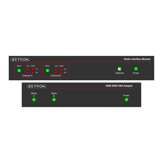
Battery charging voltage present for Radio B. When off, there is insufficient voltage for charging the battery. Power Green The iRIM adapter has power. It is off otherwise. iRIM LEDs Radio Interface Module Status Line Radio Status Line Radio Ethernet Power Channel A Channel B 025-9623 D3... - Page 51 iRIM LEDs Table 8: iRIM LED indications Indication Description Status Channel is idle. Channel is transmitting. Green Channel is receiving (and for the duration of the VOX hold time). Amber Channel is both transmitting and receiving. Line TX The LED blinks red while the iRIM is sending an FSK packet to the console system.
-
Page 52: Specifications
1.5 x 7.75 x 10.25 inches (HxWxD) Tone Remote Interface Interface Type Industry standard tone remote interface Audio 4-wire, 600W Tone Timings High Level Guard Tone: 120 ms Function Tone: 40 ms Low Level Guard Tone: duration of transmit Guard Tone Frequency: 2175 Hz 025-9623 D3... - Page 53 Tone Remote Interface...
-
Page 54: Index
Required Tools, 10 FTP Access, 43 RX Mute During TX Voice Delay, 47 Gateway, 45 safety summary, 4 Guard Tone To Console On COR, 47 Specifications, 52 System Parameters, 44 HTTP Access, 41 Talkgroup Alias, 49 Talkgroup List, 48 025-9623 D3... - Page 55 Index TX Voice Delay, 46...
Need help?
Do you have a question about the 025-9623 D3 and is the answer not in the manual?
Questions and answers