
Summary of Contents for Trumeter IOT-GATEWAY-ETH
- Page 1 GATEWAY ETHERNET/4G/LTE Quickstart Guide GlobalTestSupply www. .com Find Quality Products Online at: sales@GlobalTestSupply.com...
- Page 2 CONTENTS 1. DEVICE LIGHT SUMMARY 2. DEVICE DIAGRAM 3. HARDWARE CONFIGURATION i. Device Wiring ii. Powering Device iii. Device Mounting 4. CLOUD ACCESS i. Registering a Customer Account ii. Adding a New User iii. Adding a New Gateway iv. Editing Gateway Configuration 5. ALARM SETUP i.
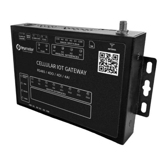
- Page 3 1. DEVICE LIGHT SUMMARY 2. DEVICE DIAGRAM Name Status 4G Gateway Ethernet Gateway 2000ms off / 300ms on No cable connection 300ms off / 300ms on COM AI4 AI3 AI2 AI1 COM DEVICE RESET No cellular network 9-36VDC - OUT R5485 ANALOG INPUT - 4-20mA 9-36VDC - IN ANTENNA/ 80mA MAX ETHERNET...
- Page 4 3. HARDWARE CONFIGURATION 4. CLOUD ACCESS i. Device Wiring 1. Wire selected APM meters 4-20ma connections to To access Trumeter Cloud dashboard, go to router 2. Wire selected APM meters digital outputs (for alarm There are two types of user account: feature) to router 1.
- Page 5 i. Registering a Customer User Account ii. Adding a New User 1. Go to 1. Go to 2. Click Sign Up to go to the registration screen 2. Login as Customer User 3. Once registered a confirmation email will be sent to 3. Go to User Groups > Self Registration Users the email address used for the account 4.
- Page 6 iii. Adding a New Gateway iv. Editing Gateway Configuration 1. Go to 1. Go to 2. Open dashboard as Customer User 2. Open dashboard as Customer User 3. Add unique serial code and model in the “add new 3. Click cog on the gateway you want to configure gateway”...
- Page 7 5. ALARM SETUP i. SMS and Email Setup 1. Set APM alarm output thresholds using APM 1. Go to configurator 2. Login as Customer User 2. E nsure wiring from APM output to Digital Input on 3. Click on the “cog” on the gateway you want to add gateway SMS or email 3.
- Page 8 6. WIRING DIAGRAM Analog 4-20mA GND/COM Digital Alarm COM AI4 AI3 AI2 AI1 COM DEVICE RESET R5485 9-36VDC - OUT ANALOG INPUT - 4-20mA ANTENNA/ 9-36VDC - IN ETHERNET 80mA MAX Dependant on Model ii. Graph Visualization and Data Export RS485 ANALOG INTERFACES 1.
Need help?
Do you have a question about the IOT-GATEWAY-ETH and is the answer not in the manual?
Questions and answers