
Related Manuals for elgris ZERO Export


Summary of Contents for elgris ZERO Export
- Page 1 ZERO Export “Universal ZERO export controller” Manual ZERO and ZEROplus Version 1.3 elgris GmbH Langerweher Str. 10 D-52459 Inden Germany www.elgrispower.com info@elgrispower.com...
-
Page 2: Table Of Contents
Broadcast ________________________________________________________________________ 14 4.3.5 SMA Smart Meter _________________________________________________________________ 14 4.3.6 SMA turbo _______________________________________________________________________ 14 4.3.7 VT value _________________________________________________________________________ 14 4.3.8 CT value _________________________________________________________________________ 14 4.3.9 Setpoint _________________________________________________________________________ 15 elgris cloud _________________________________________________________________________ 16 www.elgrispower.com Version: 5. August 2019 19:37 Page 2 of 23... - Page 3 Live chart __________________________________________________________________________ 17 Data logger _________________________________________________________________________ 18 Performance________________________________________________________________________ 18 ZEROplus __________________________________________________________________________ 19 ADJUSTING THE PID SETTINGS _______________________________________________________ 20 Manual tuning ______________________________________________________________________ 20 Ziegler–Nichols method ______________________________________________________________ 21 FIRMWARE UPDATE ___________________________________________________________________ 22 6.1. Introduction ________________________________________________________________________ 22 Connecting with the controller _________________________________________________________ 22 Start of the boot loader_______________________________________________________________ 22 Login ______________________________________________________________________________ 23 Select new firmware _________________________________________________________________ 23...
-
Page 4: Introduction
Dear customer, thank you for purchasing this product. The ZERO export controller is the first controller available on the market which can control up to 10 PV inverters with ZERO export functionality. Further the ZERO can also act a general PV output controller by limiting the production. -
Page 5: Installation
Installation Safety instructions Before installing the product in the end-installation, ensure that the device is not damages during transport and everything looks in a normal way. All the connecting cables must not be bent or squeezed. This can result in malfunctions, short circuits and defects in the device and/or sensor connected. -
Page 6: Pin Description
Pin description Description Minimum Maximum Phase 1 voltage input 85 Vac 250 Vac Phase 2 voltage input 85 Vac 250 Vac Phase 3 voltage input 85 Vac 250 Vac Neutral input of voltage 0 Vac K input current transformer L1 0 Aac 5 Aac L input current transformer L1... -
Page 7: Zeroplus
ZEROplus 11 12 13 14 18 17 16 15 The ZEROplus is a ZERO controller equipped with 4 dry contacts to control external loads before shunting the solar output. Channel Electrical limit 11 and 12 1 A at 250 VAC, 1 A at 30 VDC, resistive load 13 and 14 1 A at 250 VAC, 1 A at 30 VDC, resistive load 15 and 16... -
Page 8: Rs 485 Pin Out
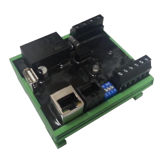
RS 485 pin out Description Not connected RS-232 TX RS-232 RX RS-485 B (D-) RS-485 A (D+) Not connected Not connected Dipswitches Dipswitch Description DHCP Static IP 50 Hz 60 Hz Three phase Single phase Not used must be OFF 2.7 LED status The LED on board informs the user about the internal status. -
Page 9: Commissioning
L1 and N in case you use a single-phase system or L1, L2 and L3 with N for three phase systems. When the ZERO export unit is working properly, the LED is blinking green or red / green flashing in case there is no internet connection, or the time server could not be reached. -
Page 10: Graphical User Interface
Graphical User Interface The ZERO export controller includes a webserver to adjust the system parameters and see the status of the system. By default, the webserver can be reached by typing the IP address 192.168.1.100 in a web browser. Supported web browsers are Microsoft Edge, Google Chrome and Mozilla Firefox. -
Page 11: Main Area
4.1.2 Main area The main area is divided into 3 parts. In the centre part, the current system layout is shown. On the left side, the donut chart with current self-consumption informs the user about how much percent of the load is covered by the PV. The right side includes a text box with the latest power readings and consumption from the grid as well as production from the PV. -
Page 12: Inverter Settings
Inverter settings After selecting the brand of the inverter which needs to be controlled, the type of communication needs to be selected. Not all communication options are available for all inverters. Please refer to the inverter support list on the website www.elgrispower.com When selecting TCP as communication, the IP address and MODBUS TCP port (Default 502) must be adjusted. -
Page 13: System Settings
System settings Status information and settings for information Basic settings like IP address and date / time Advanced settings for RS 485 bus and control parameters On the settings page the main settings and parameters can be changed. To enable the advanced settings, the checkbox must be selected. -
Page 14: Setting The Serial Baud Rate
4.3.3 Setting the serial baud rate The serial port is only used in case one inverter with RS-485 is configured in the inverter table. The speed must match the speed of the inverter. Further the number of bits and stop bits must be identical. -
Page 15: Setpoint
4.3.9 Setpoint The setpoint is used the calculate the operating point of the inverters depending on the load and PV production. There are different ways to set the setpoint. The main criteria is if the ZERO controller is connected to a single phase installation or PV inverter or a three phases system. In all cases the % setpoint is not taken for the control setpoint itself, but only for selecting of the actual value. -
Page 16: Elgris Cloud
With the elgris cloud you can store data on the open source platform emonCMS. This enables the user to have a cloud solution where all data can be visualised and transferred on other mediums. The emonCMS software can run on the open source server, a self-hosted server or local server like Raspberry PI. -
Page 17: Live Chart
Live chart The live chart shows the selected channel data with a one second interval over a fixed time window. The user can select a one, fife or fifteen minutes windows. The live chart data is not stored and only displayed on the chart. When the page is refreshed, or the channel is changed, the chart is cleared. -
Page 18: Data Logger
Data logger The data logger uses the data stored on the installed USB flash drive. When there is no flash drive available, the data logger will not show any data and return an error. Select the date to display and press “Shown” In the list on the right side, the requested channel can be selected. -
Page 19: Zeroplus
ZEROplus The elgris ZEROplus can control 4 dry contacts based on the internal measurements for the active power on all phases, phase 1, 2 or 3. When a supported PV inverter is connected to the system, the actual output of that inverter or the sum of all inverters can be used as a control input as well. -
Page 20: Adjusting The Pid Settings
Adjusting the PID settings The elgris ZERO controller has a real time PID controller to adjust the amount of PV power within the system. By setting one value to zero, P, PI or PID controllers can be set. For standard applications, the PI controller is a good starting point. -
Page 21: Ziegler-Nichols Method
Ziegler–Nichols method As in the method above, the I and D gains are first set to zero. The proportional gain is increased until it reaches the ultimate gain, Ku, at which the output of the loop starts to oscillate. Ku and the oscillation period Tu are used to set the gains as follows: Control type P value... -
Page 22: Firmware Update
6.1. Introduction This document describes how to upgrade the firmware in the elgris controller. Please read every step carefully. Not following this document could permanently damage the device. Please ensure that the power supply is stable. When the power is interrupted during the upgrade process, the controller could be damaged. -
Page 23: Login
Login To login use the credentials which come with the new firmware Select new firmware Press “Choose” to select the new firmware file and press “Upload” Reset the controller After successful updating of the firmware the following screen is shown. To activate the new firmware press “Reset controller”.
Need help?
Do you have a question about the ZERO Export and is the answer not in the manual?
Questions and answers