Advertisement
Quick Links
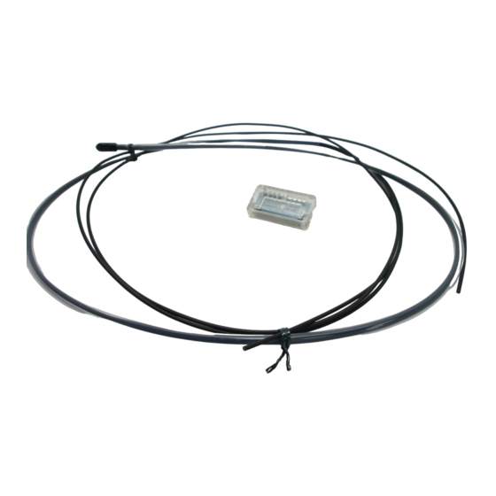
INSTRUCTION MANUAL
Liquid Level Detection Fiber
FD-F8Y
Thank you very much for using SUNX products. Please read this Instruction Manual
carefully and thoroughly for the correct and optimum use of this product. Kindly keep
this manual in a convenient place for quick reference.
Please refer to the instruction manual enclosed with the fiber sensor amplifier.
1
SPECIFICATIONS
Type
Item
Model No.
FX-301(P), FX-302(P), FX-303(P), FX-311(P), FX-D1(P), FX-A1(P), FX-M1(P)
Applicable fiber
red LED type of FX-7 series, long sensing range type of FX-10 series
amplifiers
Sensing object
Repeatability
Allowable
Tube: R40mm or more (Do not bend 26mm length from the tip)
bending radius
Fiber cable: R15mm or more
Fiber cable length
2m free-cut [Do not cut the tube (Note 2)]
Ambient temperature
-40 to +125
(No dew condensation or icing allowed), Storage: -40 to +125
(Note 3) (Note 4)
Ambient humidity
Ambient pressure
(Note 4)
Material
Tube: Fluorine resin, Fiber sheath: Polypropylene
FX-CT2 (Fiber cutter): 1 pc.
Accessory
FX-AT3 ( 2.2mm fiber attachment for FX-301/302/303/311 series): 1pc.
Notes: 1)
Unclear liquid may not be sensed stably.
2)
1,000mm from the amplifier insertion end is the cutting range.
3)
Liquid being detected should also be kept within the rated ambient
temperature range.
4)
The ambient temperature and pressure under which these devices are used
are set separately.
For usage with both of these at or near the maximum permissible value,
please contact our office.
2
CAUTIONS
Take care that unclear liquid may not be sensed stably.
Take care that the tube may stretch by maximum 2% of the total length if it is used
at a high temperature.
Bending radius of the fiber cable must be R15mm or more (tube: R40mm or
more). However, do not bend 26mm length from the tip.
If the bending radius is smaller than the specified value, the sensing performance
may deteriorate.
Do not use the fiber at places having intense vibrations, as this can cause mal-
function.
Keep the fiber head surface intact. If it is scratched or spoiled, the detectability will
deteriorate.
Ensure that any strong extraneous light is not incident on the receiving face of the
fiber head.
Do not apply excessive tensile force to the fiber cable.
Take care that the sensor is not directly exposed to fluorescent light from a rapid-
starter lamp or a high frequency lighting device, as it may affect the sensing per-
formance.
3
MOUNTING
Use a commercially available fluorine resin joint, etc.,
to install FD-F8Y.
4
CUTTING FIBER CABLE
The fiber cables should be cut off at the ends with the fiber cutter FX-CT2
(accessory) before insertion into the fiber amplifier.
For the usage of the fiber cutter (FX-CT2), refer to the instruction manual
enclosed with this product other than this instruction manual.
Do not scratch the fiber sheath while cutting the fluorine resin tube.
Protective tube
Refelctive
FD-F8Y
Liquid (Note 1)
0.5mm or less (with water)
35 to 85% RH, Storage: 35 to 85% RH
-49 to +490kPa
Fluorine resin joint
Possible
10
mm
cutting range
Fiber cable
5
SENSITIVITY SETTING
Do not move or bend the fiber cable after the sensitivity setting. Detection may
become unstable.
When using the FX-301(P) or the FX-302(P), FX-303(P)
<2-level teaching>
This is the method of setting the threshold value by teaching two levels,
corresponding to the immersed and not immersed conditions. Normally, setting is
done by this method.
Step
Display
The fibers are mounted in the tank.
Press MODE key to light up MODE indicator /
TEACH (yellow).
Press jog switch in the fiber immersed condition.
If the teaching is accepted, the read incident
light intensity blinks in the digital display.
MODE indicator / TEACH (yellow) blinks.
Press jog switch in the fiber not immersed con-
dition.
If the teaching is accepted, the read incident light intensity blinks in the digital
display and the threshold value is set at the mid-value between the incident
light intensities in the immersed and the not immersed conditions. After this,
the judgment on the stability of sensing is displayed.
In case stable sensing is possible: '
(green) blinks.
In case stable sensing is not possible: '
(green) is off.
The threshold value is displayed.
'
' blinks in the digital display.
The incident light intensity appears in the digital dispaly and the setting is
complete.
<Limit teaching>
This is the method of setting the threshold value by teaching only the water absent
condition (not immersed condition).
Step
Display
The fibers are mounted in the tank.
Press MODE key to light up MODE indicator /
TEACH (yellow).
Press jog switch in the not immersed condition.
If the teaching is accepted, the read incident
light intensity blinks in the digital display.
MODE indicator / TEACH (yellow) blinks.
Turn jog switch to the '-' side.
If jog switch is turned to the '-' side, '
the digital display from left to right, and the threshold level is
shifted to a value approx. 15% lower (higher sensitivity) than
that set at
. (Note)
High
100%
Low
0
After this, the judgment on whether the setting shift amount can be shifted or
not is displayed.
In case shifting is possible: '
In case shifting is not possible: '
The threshold value is displayed.
'
' blinks in the digital display.
The incident light intensity appears in the digital dispaly and the setting is
complete.
Note: The approx. 15% amount of shift is the initial value. The amount of shift can be
changed in the PRO mode from approx. 5 to 80% (5% step). Refer to
'SUNX fiber sensor homepage (http://www.fiber-sensor.com)' for the setting
method.
When using the FX-311(P)
Adjust the sensitivity, observing the op-
eration indicator (orange).
However, since the condition for lighting
up of the indicator depends on the com-
bination of the sensing condition and
selected operation for L/D-ON, verify it
from the table on the right.
The sensitivity adjuster is a 12-turn po-
tentiometer. The maximum sensitivity is
obtained by turning it fully clockwise.
The pointer shows the present sensitivity level.
Description
' is displayed. Stability indicator
' is displayed. Stability indicator
Description
' scrolls (twice)
OFF
Incident light intensity
with fiber not immersed
15%
Threshold value
ON
Turn to '-' side
' is displayed.
' is displayed.
: Lights up,
Sensing
MODE
condition
L-ON (ON when not immersed)
Immersed
D-ON (ON when immersed)
L-ON (ON when not immersed)
Not
immersed
D-ON (ON when immersed)
Press
Press
Press
Press
Press
Turn to '-' side
: Lights off
Operation
indicator
Advertisement

Related Manuals for Sunx FD-F8Y

Summary of Contents for Sunx FD-F8Y
- Page 1 Step Display Description Thank you very much for using SUNX products. Please read this Instruction Manual carefully and thoroughly for the correct and optimum use of this product. Kindly keep The fibers are mounted in the tank. this manual in a convenient place for quick reference.
- Page 2 When 'assist function' is not used, the middle point of is regarded case of FD-F8Y, correct threshold value setting cannot be done in full auto-teaching. as the optimum sensitivity point. If the mode selection switch is changed to 'RUN' when '...
- Page 3 Notes: 1) If the jog switch is pressed continuously 3 sec., or more, full auto-teaching is done. In case of FD-F8Y, correct sensitivity setting cannot be done in full When using the long sensing range type of FX-10 series auto-teaching.
Need help?
Do you have a question about the FD-F8Y and is the answer not in the manual?
Questions and answers