Table of Contents
Advertisement
Quick Links
Introduction
This user's guide provides setup and usage instructions for the Car Access Reference System (CARS) featuring
Remote Keyless Entry (RKE), Passive Entry/Passive Start (PEPS), Ultra-Wideband (UWB) distance measurement
and vehicle Immobilizer (IMMO) functionality, based on the Microchip's GEN2 communication protocols. It offers a
complete car access system for various car access products and its evaluation. The reference designs are both
scalable and configurable through either the PC application or source code modifications, enabling adaptation of
the basic hardware and software building blocks to meet the most recent requirements for specialized systems. For
example, the UWB reference design board is not required if the UWB functionality is not being evaluated.
Features
•
Full Car Access System Capability:
– Vehicle IMMO
– Multichannel RF RKE
– LF PEPS
– Identifying relay attack with UWB distance measurement
•
Open System Software:
– Open Immobilizer Protocol (OIP) immobilizer stack using AES-128
– RKE RF rolling code using AES-128
– PEPS protocol with a high-precision 3D localization using AES-128
– Scalable and configurable
– PC Graphical User Interface (GUI) for system visualization and viewing data communication
•
Body Computer Emulation using the SAMC21J18A XplainedPro (XPRO) Evaluation Board
©
2020-2022 Microchip Technology Inc.
and its subsidiaries
ATAK51005-V1 User's Guide
User Guide
ATAN0219
DS50003051B-page 1
Advertisement
Table of Contents

Subscribe to Our Youtube Channel
Summary of Contents for Microchip Technology ATAK51005-V1
-
Page 1: Introduction
ATAN0219 ATAK51005-V1 User's Guide Introduction This user’s guide provides setup and usage instructions for the Car Access Reference System (CARS) featuring Remote Keyless Entry (RKE), Passive Entry/Passive Start (PEPS), Ultra-Wideband (UWB) distance measurement and vehicle Immobilizer (IMMO) functionality, based on the Microchip’s GEN2 communication protocols. It offers a complete car access system for various car access products and its evaluation. -
Page 2: Table Of Contents
Programming the ATA5702 on the ATAB5702A Fob Board............36 6.2. Programming the ATA5831 on the ATA5831-XPRO Board............38 6.3. Programming the SAMC21J18A on the ATSAMC21-XPRO Board........... 40 XPRO USB Driver Installation.......................43 Document Revision History........................44 The Microchip Website..........................45 User Guide DS50003051B-page 2 © 2020-2022 Microchip Technology Inc. and its subsidiaries... - Page 3 ATAN0219 Product Change Notification Service......................45 Customer Support............................45 Microchip Devices Code Protection Feature....................45 Legal Notice..............................45 Trademarks..............................46 Quality Management System........................47 Worldwide Sales and Service........................48 User Guide DS50003051B-page 3 © 2020-2022 Microchip Technology Inc. and its subsidiaries...
-
Page 4: Quick References
Acronyms and Abbreviations Description CARS Car Access Reference System Comma Separated Variable End-of-Line Graphical User Interface IMMO Immobilizer Message Authentication Code Open Immobilizer Protocol PEPS Passive Entry/Passive Start User Guide DS50003051B-page 4 © 2020-2022 Microchip Technology Inc. and its subsidiaries... - Page 5 ATAN0219 Quick References ...continued Acronyms and Abbreviations Description Remote Keyless Entry Sub-Miniature A Time of Flight Unidirectional Authentication Unique ID Ultra-Wideband Ultra High Frequency User Guide DS50003051B-page 5 © 2020-2022 Microchip Technology Inc. and its subsidiaries...
-
Page 6: Kit Overview
The system consists of an RF receiver in the vehicle and an RF transmitter in the fob. Unlike the immobilizer operation, the RKE operation requires a battery (CR2032 or equivalent) to be inserted in the fob. User Guide DS50003051B-page 6 © 2020-2022 Microchip Technology Inc. and its subsidiaries... -
Page 7: Peps Block
PEPS message to the vehicle via the unidirectional UHF link, is beyond the configured distance threshold, then a relay attack error message displays within the GUI. The same is true if there is no UWB message response from the fob. User Guide DS50003051B-page 7 © 2020-2022 Microchip Technology Inc. and its subsidiaries... -
Page 8: Kit Setup
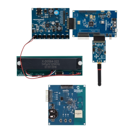
Kit Setup Kit Setup Perform the following steps to set up the ATAK51005-V1 kit: On the ATSAMC21-XPRO microcontroller board, ensure that the VCC-SEL jumper is set to the 5.0V position. If using the ATA5291-XPRO board, perform the following actions; otherwise, skip to step 3. - Page 9 ATAN0219 Kit Setup Figure 3-1. ATAK51005-V1 Kit Setup ATA5291-XPRO Board ATSAMC21-XPRO Board ATA5831-XPRO Board ATAB-LFTX LF Antenna Module UHF SMA Whip Antenna ATAB5702A Fob Board Insert the ATA5831-XPRO RF transceiver board in the EXT1 connector on the ATSAMC21-XPRO board. Connect the UHF SMA whip antenna to the ATA5831-XPRO board at the ANT2 SMA connector.
-
Page 10: Cars Kit Pc Evaluation Utility
Expand the “Ports (COM & LPT)” menu, then note the COM port assigned to the “EDBG Virtual COM Port”. In this example, COM17 is used while connecting the CARS kit evaluation utility program to the ATSAMC21- XPRO board. Figure 4-1. Virtual COM Port Assignment User Guide DS50003051B-page 10 © 2020-2022 Microchip Technology Inc. and its subsidiaries... -
Page 11: Com Port And Baud Rate Settings
COM Port and Baud Rate Settings Navigate to the folder containing the downloaded ATAK51005-V1 software files and open the CARS_PC_Application.exe file. Perform the following steps for the COM port and baud rate settings. COM Port Settings In the Car Access System PC Application window, navigate to COM >... - Page 12 Do not click the Clear button in the System Configuration window as doing so erases all stored UID values. Without the stored values, the system car access functions, PEPS authentication and RKE messaging do not operate. User Guide DS50003051B-page 12 © 2020-2022 Microchip Technology Inc. and its subsidiaries...
-
Page 13: System Operation
– “Log file” – Selecting this check box creates a new record line in a Comma Separated Variable (CSV) document for each received message when it is selected User Guide DS50003051B-page 13 © 2020-2022 Microchip Technology Inc. and its subsidiaries... -
Page 14: Remote Keyless Entry Operation
If not done so already, follow the procedure detailed in 4. CARS Kit PC Evaluation Utility. Navigate to View > RKE Messaging. The RKE Message Status window shows the following data fields: User Guide DS50003051B-page 14 © 2020-2022 Microchip Technology Inc. and its subsidiaries... -
Page 15: Peps Operation
UWB messages to the fob, which, then, responds with information via the UHF and UWB link. Note: UWB boards are not required for PEPS Operation. User Guide DS50003051B-page 15 © 2020-2022 Microchip Technology Inc. and its subsidiaries... -
Page 16: System Configuration Window Overview
To set the calibration values and provide an interface to read/write user data in each selected fob In the Car Access System PC Application window, navigate to View > System Configuration to open the System Configuration window (see the following figure). User Guide DS50003051B-page 16 © 2020-2022 Microchip Technology Inc. and its subsidiaries... - Page 17 The vehicle ID is set in the fob during the learn procedure and is user-definable. • “Learned Fobs” – This section lists up to four individual fob IDs paired with the system and saved in memory. User Guide DS50003051B-page 17 © 2020-2022 Microchip Technology Inc. and its subsidiaries...
- Page 18 Diagnostic mode by clicking the Enter Diag button. Then, for several seconds, the fob responds to read or write commands. User Guide DS50003051B-page 18 © 2020-2022 Microchip Technology Inc. and its subsidiaries...
-
Page 19: Peps Message Status Window Overview
The PEPS Message Status window contains the PEPS commands section and shows the following data fields: • “Serial Number” – Displays the received fob ID. This must correspond to the value in the Learned Fobs section of the System Configuration window. User Guide DS50003051B-page 19 © 2020-2022 Microchip Technology Inc. and its subsidiaries... -
Page 20: Identifying Fobs Within Lf Range
Fob# assignments. The “Fob Vehicle ID” field displays the returned vehicle ID. Click the S/W Ver button to send the software version request to the fob. The “S/W Ver” field displays the returned software version number. User Guide DS50003051B-page 20 © 2020-2022 Microchip Technology Inc. and its subsidiaries... -
Page 21: Fob Calibration Overview
The compensation procedure is based on the following: • “Ref. RSSI” – Denotes the internal RSSI values measured with reference conditions (end-of-line) [1] User Guide DS50003051B-page 21 © 2020-2022 Microchip Technology Inc. and its subsidiaries... -
Page 22: Fob Calibration Process
Click the Fob ID button followed by the Calibrate Fob button. Figure 5-9. FOB Calibration Click the Next button within the Fob End-of-Line (EOL) Configuration window. User Guide DS50003051B-page 22 © 2020-2022 Microchip Technology Inc. and its subsidiaries... - Page 23 “Peak RSSI” field for the X-axis. Click the Measure button several times to ensure the peak value is stable (see the following figure). Note: When using the ATA5293-XPRO, the X-10013-002 antenna positioning is the same as the LF antenna module. Click the Next button. User Guide DS50003051B-page 23 © 2020-2022 Microchip Technology Inc. and its subsidiaries...
- Page 24 (see the following figure). Note: When using the ATA5293-XPRO, the X-10013-002 antenna positioning is the same as the LF antenna module. Click the Next button. User Guide DS50003051B-page 24 © 2020-2022 Microchip Technology Inc. and its subsidiaries...
- Page 25 (see the following figure). Note: When using the ATA5293-XPRO, the X-10013-002 antenna positioning is the same as the LF antenna module. 10. Click the Next button. User Guide DS50003051B-page 25 © 2020-2022 Microchip Technology Inc. and its subsidiaries...
- Page 26 3-axis LF antenna coil circuits (see the following figure). Note: When using the ATA5293-XPRO, the X-10013-002 antenna positioning is the same as the LF antenna module. 12. Click the Next button. User Guide DS50003051B-page 26 © 2020-2022 Microchip Technology Inc. and its subsidiaries...
- Page 27 LED on the ATAB5702A fob board). Before closing the Fob EOL Configuration window, wait until the LEDs stop blinking. Note: If there is only a slight difference in the Int. RSSI values, check the No change check box. User Guide DS50003051B-page 27 © 2020-2022 Microchip Technology Inc. and its subsidiaries...
- Page 28 (for example, evaluating a different 3D coil). • Checking the “Update EEPROM” check box updates the RSSI values currently stored in the EEPROM with the newly measured values. User Guide DS50003051B-page 28 © 2020-2022 Microchip Technology Inc. and its subsidiaries...
- Page 29 “Ref. RSSI” values under the “PEPS Fob Actions” section must match the “Measured Int. RSSI” values from the Fob EOL Configuration window. Repeat the fob calibration if these values do not match. User Guide DS50003051B-page 29 © 2020-2022 Microchip Technology Inc. and its subsidiaries...
-
Page 30: Peps Wake-Up Functionality
When using the ATA5293-XPRO and antenna channel 1, the X-10013-002 antenna is required. When using antenna channels 2 through 5, the X-10013-003 antenna is required; channel 6 is not used within the PC application. User Guide DS50003051B-page 30 © 2020-2022 Microchip Technology Inc. and its subsidiaries... -
Page 31: Peps Communication
“Distance Scale (RSSI)” field of the PEPS Message Status window. Enter this value in the “In/Out Threshold” field of the System Configuration window (see Figure 5-18). User Guide DS50003051B-page 31 © 2020-2022 Microchip Technology Inc. and its subsidiaries... - Page 32 Outside the vehicle and is highlighted in pink due to the distance scale value being less than the threshold value. Figure 5-20. PEPS Bilateral Authentication with Outside Localization User Guide DS50003051B-page 32 © 2020-2022 Microchip Technology Inc. and its subsidiaries...
-
Page 33: Uwb Communication
“Relay Attack Threshold (cm)” as 20 cm and the measured value distance scale, “TOF Measured (cm)” as 34 cm, the system is experiencing a relay attack; therefore, the Relay Attack icon displays. User Guide DS50003051B-page 33 © 2020-2022 Microchip Technology Inc. and its subsidiaries... -
Page 34: Uwb Operation
If not done so already, follow the procedure detailed in 4. CARS Kit PC Evaluation Utility. Navigate to View > UWB Messaging. The UWB status window shows the following data fields: User Guide DS50003051B-page 34 © 2020-2022 Microchip Technology Inc. and its subsidiaries... - Page 35 Click the Reset Count button to clear all the fields on the UWB Status window. User Guide DS50003051B-page 35 © 2020-2022 Microchip Technology Inc. and its subsidiaries...
-
Page 36: Programming Instructions
– ATAB5702A fob board: PEPS, IMMO and RKE firmware in Flash and configuration in the EEPROM Note: All devices within this system are shipped unprogrammed; therefore, the programming procedure is described in the following sections. Programming is also required when the revised ATAK51005-V1 tool package software is available for download from www.microchip.com/developmenttools/ProductDetails/ATAK51005-V1... - Page 37 Note: If the EEPROM verification fails (as shown in the following figure), repeat steps 1-10 to ensure the configuration is correct. If the error still occurs, then the ATA5702 IC version is outdated and the user must contact their local sales representative for an upgrade. User Guide DS50003051B-page 37 © 2020-2022 Microchip Technology Inc. and its subsidiaries...
-
Page 38: Programming The Ata5831 On The Ata5831-Xpro Board
Select the Tool, Device and Interface, as shown in the following figure, then click Apply. Figure 6-9. ATA5831 Device Selection Ensure that the ISP frequency is less than 100 kHz. Click Set. User Guide DS50003051B-page 38 © 2020-2022 Microchip Technology Inc. and its subsidiaries... - Page 39 Select the Fuses tab and verify that the proper fuse settings exist. If not, change them to match the following figure, then click the Program button. Figure 6-12. ATA5831 Fuse Settings Select the Memories tab, then click the Erase now button. User Guide DS50003051B-page 39 © 2020-2022 Microchip Technology Inc. and its subsidiaries...
-
Page 40: Programming The Samc21J18A On The Atsamc21-Xpro Board
ATSAMC21-XPRO board is in place. The following steps use the embedded debugger (EDBG) on the board for programming: In Atmel Studio 7, navigate to Tools > Device Programming. Select the Tool, Device and Interface, as shown in the following figure, then click Apply. User Guide DS50003051B-page 40 © 2020-2022 Microchip Technology Inc. and its subsidiaries... - Page 41 User Word 0.NVMCTRL EEPROM SIZE, which must be set to 4096 bytes. Click the Program button. Figure 6-17. SAMC21J18A Fuse Settings Select the Memories tab, then click the Erase now button. Figure 6-18. SAMC21J18A Memory Settings Browse to locate the ATAK51005-V1.hex file for the flash memory image. User Guide DS50003051B-page 41 ©...
- Page 42 ATAN0219 Programming Instructions Click the Program button, then wait for completion. User Guide DS50003051B-page 42 © 2020-2022 Microchip Technology Inc. and its subsidiaries...
-
Page 43: Xpro Usb Driver Installation
The necessary USB drivers to interface with the ATSAMC21-XPRO are included with the Atmel Studio integrated software development environment (www.microchip.com/mplab/avr-support/atmel-studio-7). Download and install this software development utility to get the USB drivers needed for the CARS kit evaluation utility. User Guide DS50003051B-page 43 © 2020-2022 Microchip Technology Inc. and its subsidiaries... -
Page 44: Document Revision History
4. CARS Kit PC Evaluation Updated content along with Utility latest figures 5. System Operation • Updated chapter • Updated with latest images Added 5.3.8. UWB Communication Added 5.4. UWB Operation User Guide DS50003051B-page 44 © 2020-2022 Microchip Technology Inc. and its subsidiaries... -
Page 45: The Microchip Website
It is your responsibility to ensure that your application meets with your specifications. Contact your local Microchip sales office for additional support or, obtain additional support at www.microchip.com/en-us/support/ design-help/client-support-services. User Guide DS50003051B-page 45 © 2020-2022 Microchip Technology Inc. and its subsidiaries... -
Page 46: Trademarks
The Adaptec logo, Frequency on Demand, Silicon Storage Technology, Symmcom, and Trusted Time are registered trademarks of Microchip Technology Inc. in other countries. GestIC is a registered trademark of Microchip Technology Germany II GmbH & Co. KG, a subsidiary of Microchip Technology Inc., in other countries. -
Page 47: Quality Management System
ATAN0219 Quality Management System For information regarding Microchip’s Quality Management Systems, please visit www.microchip.com/quality. User Guide DS50003051B-page 47 © 2020-2022 Microchip Technology Inc. and its subsidiaries... -
Page 48: Worldwide Sales And Service
Tel: 631-435-6000 Sweden - Stockholm San Jose, CA Tel: 46-8-5090-4654 Tel: 408-735-9110 UK - Wokingham Tel: 408-436-4270 Tel: 44-118-921-5800 Canada - Toronto Fax: 44-118-921-5820 Tel: 905-695-1980 Fax: 905-695-2078 User Guide DS50003051B-page 48 © 2020-2022 Microchip Technology Inc. and its subsidiaries...
Need help?
Do you have a question about the ATAK51005-V1 and is the answer not in the manual?
Questions and answers