Table of Contents
Advertisement
Quick Links
Advertisement
Table of Contents

Summary of Contents for Control Technology Inc. 2500 Series
- Page 2 Copyright © 2014 Control Technology Inc. All rights reserved. This manual is published by Control Technology Inc., 5734 Middlebrook Pike, Knoxville, TN 37921. This manual contains references to brand and product names which are trade names, trademarks, and/or registered trademarks of Control Technology Inc. Siemens® and SIMATIC® are registered trademarks of Siemens AG.
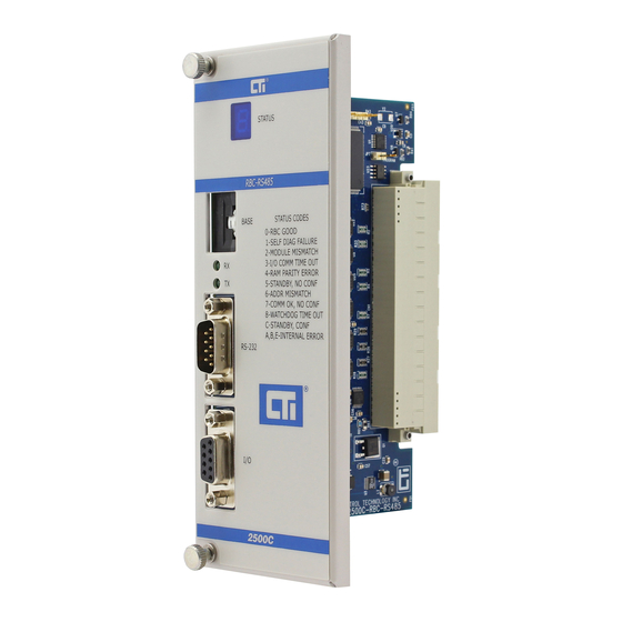
- Page 3 This Installation and Operation Guide provides reference information for the CTI 2500C-RBC- RS485 RS485 Remote Base Controller. The information in this manual is directed to individuals who will be installing the module and configuring it for use with a CTI 2500 Series® or Simatic® 505 Processor.
- Page 4 NOTE: Notes alert the user to special features or procedures. CAUTION: Cautions alert the user to procedures that could damage equipment. WARNING: Warnings alert the user to procedures that could damage equipment and endanger the user. CTI 2500C-RBC-RS485 Installation and Operation Guide V1.1...
-
Page 5: Table Of Contents
CHAPTER 1. DESCRIPTION..................5 Introduction.....................5 Communication Ports..................5 1.2.1 Serial Port 1.2.2 I/O Port CHAPTER 2. INSTALLATION................7 Installation Planning ..................7 2.1.1 Choosing Remote I/O Media 2.1.2 Selecting a Remote Base Address 2.1.3 Setting Module Hardware Options 2.1.4 Connecting to Remote I/O Cable Unpacking the Module ...................7 2500-RBC-RS485 Module Board Layout............8 2500C-RBC-RS485 Front Panel Layout ............9... - Page 6 Figure 1. 2500C-RBC-RS485 Front Panel................5 Figure 2. 2500C-RBC-RS485 2500C-RBC-RS485 Module Board Layout ......8 Figure 3. 2500C-RBC-RS485 Front Panel................9 Figure 4. 2500C-RBC-RS485 Front Panel................10 Figure 5. 2500C-RBC-RS485 Freeze Jumper Selection Jumper .........11 Figure 6. 2500C-RBC-RS485 Serial Port Pin outs...............13 Figure 7. 2500C-RBC-RS485 Serial Port Pin outs...............13 Figure 8.
-
Page 7: Chapter 1. Description
I/O modules compatible with programmable controllers from Siemens® and CTI. The 2500C-RBC-RS485 RS485 Remote Base Controller (RBC) allows a 2500 Series® Compact I/O base to function as a remote base. It provides the following functions: Compatible with CTI 2500 Series® and Simatic®... -
Page 8: Serial Port
1.2.1 Serial Port The RS232 port is provided to interface to PLC programming and configuration tools such as TISOFT . A standard 9-pin PC-compatible RS232 serial cable is used to connect to the programming device or modem. The port pinout is provided in Section 2.6 of this manual. 1.2.2 I/O Port The I/O Port connects the 2500C-RBC-RS485 to a SIMATIC®... -
Page 9: Chapter 2. Installation
Before proceeding, you must determine what address you will assign to the RBC. Remote Base addresses range from 1 to 15. In CTI 2500 Series® and Simatic® 505® systems, address 0 is reserved for the local base where the CPU is installed. Note that each Remote Base on the Remote I/O channel must have a unique address 2.1.3... -
Page 10: 2500-Rbc-Rs485 Module Board Layout
2500-RBC-RS485 Module Board Layout Freeze Jumper JP4 Module Front Panel Backplane Connector Serial Port Baud Rate Selection Switches Figure 2. 2500C-RBC-RS485 2500C-RBC-RS485 Module Board Layout CTI 2500C-RBC-RS485 Installation and Operation Guide V1.1... -
Page 11: 2500C-Rbc-Rs485 Front Panel Layout
2500C-RBC-RS485 Front Panel Layout Status Indicator RBC Address Selection Thumbwheel Switch Serial RS-232 9pin Port Remote RS-485 9pin Port Figure 3. 2500C-RBC-RS485 Front Panel CTI 2500C-RBC-RS485 Installation and Operation Guide V1.1... -
Page 12: Configuring The Module
Configuring the Module There are three steps to configuring the module and making it fully operational: 1. Setting the RS232 Port baud rate 2. Setting the Remote Base Controller address 3. Setting the output state on communication loss (Freeze Jumper) Figure 2. -
Page 13: Setting The Output State On Communication Loss
2.5.2 Setting the Output State on Communication Loss When I/O channel communication to a remote base is lost, the state of the discrete outputs is determined Figure 5. 2500C-RBC- by the selection made on the 2500C-RBC-RS485 jumper JP4 (Off/Freeze). RS485 Freeze Jumper Selection Jumper shows the location of the jumper on the 2500C-RBC-RS485. -
Page 14: Setting The Remote Controller Base Station Address
I/O station identification. A maximum of 15 remote bases can be connected to the CTI 2500 Series® CPU or Siemens® 545/555/575 CPU. NOTE: When connecting the 2500C-RBC-RS485 to a CTI 2500 Series® CPU or Siemens® 545/555/575 CPU, only addresses between 1 and 15 are valid. Each installed 2500C-RBC- RS485 must have a unique station number. -
Page 15: Connecting To The Rs232 Port
Connecting the Remote I/O Cable The I/O Port connects the 2500C-RBC-RS485 to a SIMATIC® 505 compatible RS485 Remote I/O channel. This enables the remote CTI 2500 Series® or Simatic® 505® CPU to control the I/O modules in the base where the RBC is located. -
Page 16: Operation Of Led Display
Operation of LED Display The LED Display is used to indicate the status of the 2500C-RBC-RS485 Remote Base Controller as shown in the following table: Display Definition Communications Comment / Action to RBC Module Ready Fully Operational and online with CPU. Diagnostics Failure None Serious malfunction. -
Page 17: System Status Words
STW471-485 Remote base abnormal logoff counts STW487-501 Remote base timeout counts More complete information and a list of the 2500 Series® Processor System Status Words can be found in the 2500 Series® Processor Installation and Operation Guide: http://www.controltechnology.com/Files/Products/2500-(Classic)/2500-Cxxx/manuals/CTI- 2500-IOG-(62-370) CTI 2500C-RBC-RS485 Installation and Operation Guide V1.1... -
Page 18: Appendix A. Remote I/O Installation Guidelines
Appendix A. REMOTE I/O INSTALLATION GUIDELINES These Remote I/O Installation Guidelines are based on standard RS485 wiring practices. The Remote I/O cable system consists of a main trunk line and drop lines which connect the CPU/Local Base and Remote Base(s) to the trunk line by means of terminal blocks as shown in Figure 8. -
Page 19: 3. Cable Lengths
CTI recommends Belden 3105A cable for wiring remote I/O. The following table contains the general recommended cable specs for RS485 remote I/O wiring and the preferred Beldon cable type specifications. Cable Characteristic Recommended Belden® 3105A Conductors 18AWG to 22AWG uniform 2-conductors,22AWG,.030 twisted-pair in (7.5mm), 7x30 stranded... - Page 20 Maximum Cable Length in Number of Installed Feet (Meters) Drop Lines Belden 3105A 2200 (670) 2133 (650) 2067 (630) 2000 (610) 1933 (589) 1867 (569) 1800 (548) 1733 (528) 1667 (508) 1600 (488) 1533 (467) 1467 (447) 1400 (427) Number of Maximum Distance Drop Lines Belden 9182...
-
Page 21: 4. Bus Termination
Cable trunk length is measured from the CPU to the most distant base. Terminating Terminating Resistor Max Trunk Length Resistor T = Terminal Block Figure 9. Trunk Length Measurement By using a T-configuration as shown in Figure 10. T-Connection Trunk Length, the maximum trunk length can be extended to twice the length shown in the table on the previous page. -
Page 22: 5. Cable Routing And Layout Guidelines
A. 5. Cable Routing and Layout Guidelines Cables containing the following should be routed Bus signals, e.g. Remote I/O Data signals for PCs, programming devices, printers etc. Screened analog inputs Unscreened DC voltages (<= 60V) in the same cable loom or cable duct Screened process signals (<= 25 V) Unscreened AC voltages (<= 25V) Coaxial cables for monitors... - Page 23 Appendix B. The 2500C-RBC-RS485 Remote Base Controller is designed to place the I/O on its base into ilures involving the PLC processor and communications cabling. The safe state for the I/O depends on the setting of the FREEZE jumper (see 2.5.2 Setting the Output State on Communication Loss). The following situations will cause the outputs go to the safe state: 1.
-
Page 24: Appendix C. Specifications
Appendix C. SPECIFICATIONS General Module Size: Double-Wide Backplane Power Consumption: 2.5 watts Compatibility: CTI 2500 Series® and Simatic® 505® All currently-available CTI and Siemens ® 505 4-, 8-, 11-, and 16-slot bases Single and Dual-Media configurations Display: Shows RBC status and error codes... -
Page 25: Appendix D. Limited Product Warranty
Appendix D. LIMITED PRODUCT WARRANTY For product Warranty information, please see our standard product warranty at http://www.controltechnology.com/support/warranty/ In the event that the Product should fail during or after the warranty period, a Return Material Authorization (RMA) number can be requested orally or in writing from CTI main offices. Whether this equipment is in or out of warranty, a Purchase Order number provided to CTI when requesting the RMA number will aid in expediting the repair process.
Need help?
Do you have a question about the 2500 Series and is the answer not in the manual?
Questions and answers