Table of Contents
Advertisement
Quick Links
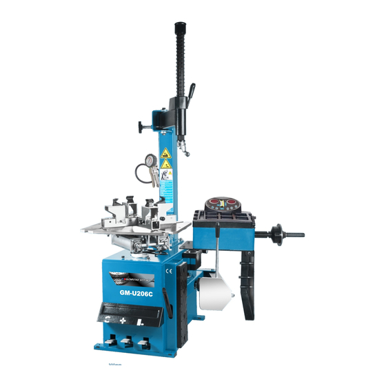
GM - U206C ALL-IN-ONE Tyre Changer & Wheel Balancer
1.
As shown in figure, assemble the base plate (1) and the bracket (2) with three pieces M10 bolts, and then fixed the base
plate (1) on the tyre changer (3) with two pieces M10 bolts.
2.
Adjust the bolt (5) to make the base plate (1) at the horizontal.
3.
Put the wheel balancer (4) on the base plate (1), and make the mounting holes aligned. Fix them with 3 pieces M8 bolts
Installed the tools hang (7) on the bracket (2).
4.
NO
Parts' Name
1
Base plate
2
3
Tyre changer
4
Wheel balancer
Parts' Code
PX-110M-020600-0
Bracket
PX-110M-020700-0
GM-U206
NO
5
6
7
U-110
1
Parts' Name
Parts' Code
Bolt
M10*25
Bolt
M8*30
Tools hang
P-000-009000-0
206M 201805
Advertisement
Chapters
Table of Contents
Troubleshooting

Summary of Contents for Glomstad Motor GM-U206C
- Page 1 206M 201805 GM - U206C ALL-IN-ONE Tyre Changer & Wheel Balancer As shown in figure, assemble the base plate (1) and the bracket (2) with three pieces M10 bolts, and then fixed the base plate (1) on the tyre changer (3) with two pieces M10 bolts. Adjust the bolt (5) to make the base plate (1) at the horizontal.
-
Page 2: Table Of Contents
206M 201805 TYRE CHANGER INSTRUCTION MANUAL INDEX PAGE 1. Introduction: ..................................3 2. Safety Warnings: ..................................3 3. Technical data ..................................4 4. Transport: ....................................4 5. Unpacking & Inspection: ............................... 4 6. Workplace requirements: ............................... 4 7. Position and installation: ............................... 5 8. -
Page 3: Introduction
206M 201805 Tyre Changer Warning This instruction manual is important for the machine, please read carefully before installation and use; also it is important for safe use and machine maintenance of machine. Please keep this manual properly in order to further maintenance of the machine. -
Page 4: Technical Data
206M 201805 3. Technical data External locking rim dimensions 6~24" Max. Wheel diameter 1040mm(41") Max. Wheel width 270mm(10") Working Pressure 8-10bar Power supply 110V (1ph)/ 220V (1ph)/ 380V (3ph) Optional Motor power 0.75/1.1 kw Max. Rotating Torque (Turntable) 1078 Nm Overall Dimension 960*760*1080mm Noise Level... -
Page 5: Position And Installation
206M 201805 7. Position and installation: 1. Unscrew the nuts at the bottom, position the machine and calibrate it with the horizontal rule. Mount the machine with all the screws and to ensure the machine is stable. Make sure the system is equipped with a good grounding circuit for prevent electric leakage. -
Page 6: Breaking The Tyre Bead
206M 201805 9.1. Breaking the tyre bead: Ensure to exhaust the air in the tyre completely, place the tyre against the rubber buffer (S). Bring the paddle against the bead about 10mm from the edge of the rim shown as Fig 5. -
Page 7: Inflating The Tire
206M 201805 Caution: When clamp the wheel rim, don't put your hands on the wheel rim to avoid injury during this operation. Lock the Hexagonal Vertical Mounting Arm, put the tyre on the rim, let the Rocker Arm back to place as demounting the tyre. - Page 8 206M 201805 spare parts provided by manufacturer. Clean the machine once every day after work. Clean the dirt on the turntable with diesel oil once per week and lubricate the slides and jaws. Following maintenance must be done at least once per month: Check oil level in Oil Fog Maker, please be filled with SAE30# oil if need.
-
Page 9: Trouble Shooting Table
206M 201805 13. Trouble shooting table: Problem Reason Solution Reverse Switch broken Replace the Reverse Switch Belt broken Replace the belt The turntable rotates just in one Check the motor cable or terminal direction or can’t rotate. The Motor’s malfunction block wire;... - Page 10 206M 201805 200-10 We can see the code “12” from the picture, then find out all the information of code “12” and record them. B-027-060401-0 Grounding screw M6x40 C-200-580000-0 Lifting level 200-13 C-200-360000-0 Bead breaker arm spring The recorded information: C-200-580000-0 Lifting level 3.
-
Page 11: Wearing Spare Parts List
206M 201805 15. Wearing spare parts list Code Order code Name Code Order code Name 200-10 C-200-500000-0 Bead breaker buffer S-000-019262-0 O- seal Ø 19.6*2.62 S-005-020075-0 V seal 20*28*7.5 200-426 S-060-016000-1 Reverse switch S-000-063265-0 O seal 63*2.65 S-000-030355-0 seal Ø 30*3.55 Clamping cylinder piston 200-228 C-200-540000-0... -
Page 12: Exploded Drawing
206M 201805 16. Exploded drawing: 239-22 200-1 CX-200-010000-0 Machine body 200-10 C-200-500000-0 Bead breaker buffer Grounding screw 200-2 CX-200-080000-0 Pedal front cover B-027-060401-0 M6x40 200-3 CX-200-020000-0 Left cover C-200-580000-0 Lifting lever Hex socket head bolt B-010-060101-0 M6×10 Flat washer Bead breaker arm B-040-061412-1 200-14 C-200-510000-0... - Page 13 206M 201805 600-101 CX-204-250000-0 Square column 200-102 CX-200-190000-0 Swing arm pin B-014-140301-0 Outer hex bolt M14x30 B-050-140000-0 Spring washer Ø14 CX-200-140000-0 Big washer 200-106 C-200-350000-0 Column adjust handle Hex socket head bolt M10× B-010-100501-0 200-120 C-200-490000-0 Vertical arm cap 200 200-121 C-200-390000-0 Vertical arm spring...
- Page 14 206M 201805 221-201 CX-221-130000-0 Turntable assembly 630 200-204 C-200-570000-0 CX-200-140000-0 Big washer B-050-160000-0 Spring washer Ø16 B-014-160401-0 Outer hex bolt M16×40 C-200-440000-0 Turntable cap Connection rod assembly 200-209 CX-200-310000-0 200-210 CX-200-280000-0 Square turntable 540 CX-200-290000-0 Square turntable washer B-055-650001-0 Snap ring Ø65(shaft) 200-221 206-214 CX-206-110100-0...
- Page 15 206M 201805 200-321 353 354 358 C-200-360000-0 Bead breaker arm spring B-055-160001-0 Snap ring Ø16 200-13 Hex socket head boltM14× B-010-140301-0 200-321 S-000-175500-0 200-301 O-seal Ø170.8x5.3 B-001-060001-0 Self-locking nut M6 200-322 CX-200-030000-0 bead breaker arm 200 S-018-010408-0 Union (90°) 1/4-Ø8 200-323 CX-200-040000-0 Bead breaker pin...
- Page 16 206M 201805 B-050-140000-0 Spring washer Ø14 200-334 CW-108-020000-0 Complete bead breaker cylinder C-2098-600500-0 Pressure spring 200-480...
- Page 17 206M 201805 200-401 C-200-060400-0 Reverse switch pedal B-040-061210-1 Flat washer Ø 6X12X1 221-402 C-221-060300-0 5-way valve pedal(right) B-040-040000-1 Flat washer Ø 4 Cross-round head screw B-055-120001-0 Snap ring Ø12(shaft) B-024-040161-0 M4*16 B-040-122520-1 Flat washer Ø12X25X2 200-431 C-200-530000-0 Reverse switch handle B-017-040301-0 Cross head screw M4X30 B-001-060001-0...
- Page 18 206M 201805 C-300-320302-0 Gear box lower cover 200-501 S-040-030204-0 Bearing 30204 S-005-020080-1 Gear box seal φ20*35*8 C-200-320500-0 Gear Belt pulley 200-504 B-014-080251-0 Outer hex bolt M8x25 B-065-006020-0 Key washer 6×20 C-200-320400-0 Worm rod 200-507 S-040-006010-0 Bearing 6010 C-200-320200-0 Worm gear shaft 200-509 C-200-320100-0 Worm gear...
- Page 19 206M 201805 C-200-320500-0 Gear Belt pulley 200-504 Motor 220V/50HZ 601-MC Motor 220v 601-MY CX-200-330000-0 Motor Belt pulley 200-602 Hex socket head bolt M8× B-007-080121-0 S-042-000686-0 Tyre changer belt A-28 B-014-080651-0 Outer hex bolt M8X65 B-040-083030-1 Flat washer Ø8*30*3 S-063-008000-0 Capacitor 80μf,110V 607-80 S-063-005000-0 Capacitor 50μf,220V...
-
Page 20: Circuit Diagram
206M 201805 17. Circuit diagram: 18. Pneumatic drawing:... - Page 21 206M 201805 WHEEL BALANCING MACHINE INSTRUCTION MANUAL Introduction……………………………………………………………………………………………………...22 Specification and Features ……………………………………………………………………………………22 2.1 Specification…………………………………………………………………………………………………22 2.2 Features ……………………………………………………………………………………………………23 2.3 Working Environment…………………………………………………………………………………… .23 The Structure of Dynamic Balancer …………………………………………………………………………23 3.1 Mechanical section …………………………………………………………………………………………23 3.2 Electrical system …………………………………………………………………………………………23 Installation of Dynamic Balancer …………………………………………………………………………23 4.1 Opening and Checking……………………………………………………………………………………...23 4.2 Installing machine……………………………………………………………………………………………24 4.3 Installing screw rod ………………………………………………………………………………………….24...
-
Page 22: Introduction
206M 201805 14. Maintenance ………………………………………………………………………………………………………36 14.1 The daily maintenance of non- professionals……………………………………………………………….36 14.2 The maintenance of professionals ………………………………………………………………………36 15. Trouble-error code list ……………………………………………………………………………………………37 16. Exploded drawings ……………………………………………………………………………………………38 17. Spare parts list …………………………………………………………………………………………………40 1. Introduction An imbalanced wheel will make the wheel jump and steering wheel wobble while driving. It can baffle the driver to drive, aggrandize the cleft of combine area of steering system, damage the vibration damper and steering parts, and increase the probability of the traffic accidents. -
Page 23: Features
206M 201805 Net weight:30Kg Dimensions: 2.2 Features Adopt 6 LED display, it has flexible interface operating function; Energy saving, motor free, hand spin; Various balancing modes can carry out counterweights to stick, clamp, or hidden stick etc;... -
Page 24: Installing Machine
206M 201805 please do not use the equipment and contact with the supplier. Standard accessories with equipment are shown as follow: Screw stud of drive axis 1 Balancing pliers Allen wrench Measure caliper Quick release nut Cone Counterweight (100g) 4.2 Installing machine 4.2.1The balancer must be installed on firm platform which is more than 60CM high and fixed with 3pcs M8 screws 4.2.2 There should be 500mm around the balancer in order to operate conveniently... -
Page 25: Main Keys And Keys Combination Function
206M 201805 Fig 5-1 1- Digital readout, amount of imbalance, inside 2- Digital readout, amount of imbalance, outside 3- Balancing mode 4- Push buttons, manual DISTANCE setting 5- Push buttons, manual WIDTH setting 6- Push buttons, manual DIAMETER setting 7- Show real imbalance amount ( less than 5gram ), function key ①gram/ounce ②mm/inch ③self-calibration 8- Push button, re-calculation 9- Function key of selecting balancing mode... -
Page 26: Installation And Demounting Of The Wheel
206M 201805 [MODE] Function key of selecting balancing mode [FINE]+ [SET] Self-calibration [FINE]+ [a↑] + [a↓] conversion between gram and ounce [SET] + [MODE] Self-testing [FINE] + [MODE] Machine setting NOTE: 1. After selection of gram or ounce, setting can remain after machine power off 2、Choose unit of mm for rim width and diameter, setting cannot remain after machine power off 6. -
Page 27: Data Of Wheel Input Method For Normal Dynamic Balance Mode And Wheel Balancing Operation
206M 201805 will be finished after two seconds. The machine enters normal dynamic balancing mode(clamp counterweights on the both rim edge) automatically, as in Fig 7-1, ready for input data of rim Fig 7-1 7.2 Data of wheel input method for normal dynamic balance mode and wheel balancing operation 7.2.1After power is on, machine enters normal balancing mode, as below figure 7.2.2Input rim data:... -
Page 28: Static (St) Balancing Mode Data Input Method And Balancing Operation
206M 201805 Fig 7-3 Fig 7-4 7.3 Static (ST) balancing mode data input method and balancing operation (ST)mode is suitable for rims on which weights only can be sticked at middle position, such as motorcycle rims. Under normal mode, measure diameter d value ( Fig 7-5 ),press [d-] or [d+] to input d value.(a value and b value can be any value ). -
Page 29: Alu-2 Mode Data Input Method And Balancing Operation
206M 201805 Input rim data, manually rotate wheel, when display shows “RUN ---”, move hand away to let wheel rotate. When display shows “STOP”, wheel stops and display shows data. Slowly rotate wheel, when inside position indication LEDs all light, (Fig 5-1(10) ), at the 12 o’clock position of rim inside edge , stick weights equal to value shown on the left side display (Fig 7-7 left)... -
Page 30: Alu-S Mode Data Input Method And Balancing Operation
206M 201805 enter ALU-3 mode to balance wheel Input rim data, manually rotate wheel, when display shows “RUN ---”, move hand away to let wheel rotate. When display shows “STOP”, wheel stops and display shows data. Slowly rotate wheel, when inside position indication LEDs all light, (Fig 5-1(10) ), at the 12 o’clock position of rim inside edge , clamp weights equal to value shown on the left side display(Fig 7-9 left)... -
Page 31: Counterweight Split And Hidden-Stick Mode
206M 201805 Fig 7-9 Input rim data, manually rotate wheel, when display shows “RUN ---”, move hand away to let wheel rotate. When display shows “STOP”, wheel stops and display shows data. Slowly rotate wheel, when inside position indication LEDs all light, (Fig 5-1(10) ), at the 12 o’clock position of rim inside aI position, stick weights equal to value shown on the left side display. -
Page 32: Self-Calibrating Of Dynamic Balancer
206M 201805 imbalance optimize Imbalance optimize have two operation method: 8.1 Already display balance value If already finish balance testing, when you need process imbalance optimize, press OPT key, display Fig 8-1; Fig 8-1 Use chalk mark a reference point on the flange and rim and tyre, use tyre changer to exchange rim and tyre by 180°... -
Page 33: Gram-Oz Conversion Operation
206M 201805 parameter may vary because of long-distance transportation or long-term use, which may cause error. Therefore, users can make self-calibrating after a period of time. 9.1 After the power-on of the machine, the initialization is finished (Fig 7-1), install a middle size balanced rim which can be clamped with counterweight, follow 7.2 to input data of rim;... -
Page 34: Key-Tone Clue On Function Settings
206M 201805 gram, displayed result will be 0, press [b-] or [b+] key to set minimum display value : 5,10 or15. Press [a+] key to save current setting and enter next step. Fig 11-1 11.2 Key-tone clue on function settings This function can turn on or off key-tone. -
Page 35: Position Sensor Signal Check
206M 201805 whether LEDs or indicator light are damaged. Checking ends and display shows Fig 11-1. Enter position sensor signal check. Press [SET] key to exit. 12.2 Position sensor signal check This function can check whether position sensor, main shaft, main board circuit are with error. -
Page 36: Maintenance
206M 201805 Hint: check precision right method: Input right date of wheel(a. b. d value),consult instruction do a self-calibration, process balance operation, note down date of first time, clamp 100 gram counterweight on the outside edge of wheel(when outside indicator light all on is top zenith position), again process balance operation, this data of outside display addition data of first time, should be 100±2, manually slowly rotate the wheel, when light of outside all on, check 100 gram counterweight whether at 6... -
Page 37: Trouble-Error Code List
206M 201805 Fig14-1 15. Trouble-error code list When balancer display hint of error, can follow consult below list to remove the trouble: Code meanings cause remedy Err 1 principal axis not spin or 1. computer board fault 1.change computer board have not spin signal 2.connection-peg untouched 2.check cable... -
Page 38: Exploded Drawings
206M 201805 Err 8 Self-calibration memory 1. not put 100 gram on the 1.follow right method fault rim when self-calibration repeat self-calibration 2. power supply board fault 2. change power supply 3. computer board fault board 4. press sensor fault 3. - Page 39 206M 201805 100-312 100-315 100-315 100-317...
-
Page 40: Spare Parts List
206M 201805 17. Spare parts list Code Description Code Description S-052-000012-0 Power Adapter P-100-170000-A Plastic bush Power Interface P-100-210000-0 Spring P-110-190000-0 Head with tools-tray Y-004-000070-0 Graduated strip S-115-001100-0 Key board P-100-900000-0 Rim distance gauge P-110-110000-0 Key fixed plate B-061-004030-0 PZ-000-010110-0 Computer board B-004-100001-2 S-036-404500-0...
Need help?
Do you have a question about the GM-U206C and is the answer not in the manual?
Questions and answers