
Summary of Contents for SSK SSK513
- Page 1 SSK 513 Electromagentic Flow Meter Installation & Operation Manual IOM-113-01-EN (2014) 51301-113 Rev.1...
- Page 2 Electromagnetic Flow Meter Page 2 March 2014...
-
Page 3: Table Of Contents
Opening the SSK513 Cover ........ - Page 4 ....... SETTING UP THE SSK WITH QUICK SETUP ........
-
Page 5: Safety Precautions And Instructions
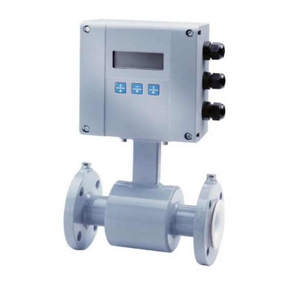
Caution indicates the potential for minor personal injury or property damage. Comply with the instructions and proceed with care. SYSTEM DESCRIPTION The SSK513 electromagnetic flow meter is intended for fluid metering in most industries including water, wastewater, food and beverage, pharmaceutical and chemical. The basic components of an electromagnetic flow meter are: •... -
Page 6: Unpacking And Inspection
If the unit was damaged in transit, it is your responsibility to request an inspection report from the carrier within 48 OTE: hours. You must then file a claim with the carrier and contact SSK for appropriate repairs or replacement. •... - Page 7 Installation & Operation Manual • Use the sling-rigged method to lift large detectors into a vertical position while they are still crated. Use this method to position while they are still crated. Use this method to position large detectors vertically into pipelines. Figure 3: Sling-Rigged Lifting Methods •...
-
Page 8: Meter Location, Orientation And Applications
Electromagnetic Flow Meter METER LOCATION, ORIENTATION AND APPLICATIONS The SSK provides two amplifier mounting options: an integral or meter mount option and a junction box/remote option . Meter mount amplifier l fi Junction box with remote amplifier l fi Figure 5: Amplifier Mounting Options The amplifier can be installed and operated outdoors. -
Page 9: Meter Orientation
Horizontal Placement SSK513 are equipped with an Empty Pipe Detection feature. If an electrode mounted in the pipe is not covered by fluid for five seconds, the meter will display an Empty Pipe Detection condition. The meter will send out an error message and stop measuring flow When the electrode is again covered with fluid, the error message disappears and the meter will begin... -
Page 10: Straight Pipe Requirements
Electromagnetic Flow Meter Straight Pipe Requirements Sufficient straight-pipe runs are required at the detector inlet and outlet for optimum meter accuracy and performance. An equivalent of three diameters of straight pipe is required on the inlet (upstream) side. Two diameters are required on the outlet (downstream) side. -
Page 11: Chemical Injection Applications
Installation & Operation Manual Chemical Injection Applications For water line applications with a chemical injection point, install the meter upstream of the injection point. This eliminates any meter performance issues. FLOWMETER CHEMICAL INJECTION HERE FORWARD FLOW UPSTREAM DOWNSTREAM Figure 10: Chemical Injection Point Upstream of Meter If a meter must be installed downstream of a chemical injection connection, the distance between the meter and the injection point should be between 50 and 100 feet (15 and 30 meters). -
Page 12: Partially-Filled Pipe Situations
Electromagnetic Flow Meter Partially-Filled Pipe Situations In some locations, the process pipe may be momentarily only partially filled. Examples include: lack of back pressure, insufficient line pressure and gravity flow applications. To eliminate these situations, do not install the meter at the highest point of the pipeline. WRONG Figure 12: Incorrect Meter Placement Do not install the meter in a vertical, downward flow section of pipe. -
Page 13: Meter Gaskets And Grounding
Conductive Pipe Grounding To achieve an adequate ground, the meter body MUST be electrically connected to the liquid media. The SSK flanges are provided with grounding bolts for this purpose. -
Page 14: Non-Conductive Pipe Grounding
Electromagnetic Flow Meter Non-Conductive Pipe Grounding IMPORTANT If the process pipe is not electrically conductive (PVC, fiberglass, cement-lined pipes or any other non-conductive material) and the meter was not originally ordered with an optional grounding electrode, you must install a pair of grounding rings between the mating flanges at both ends of the meter. -
Page 15: Wiring
• Use twisted pair shielded wire for all output wiring. • Observe all applicable, local electrical codes. Opening the SSK Cover The SSK amplifier's design lets you open the cover without completely removing it . Cover is attached with display ribbon cable. -
Page 16: External Disconnect
Remove the junction box lid. Carefully remove the wires connected to the terminal blocks that run to the SSK . See the chart below for a reference of wire color to terminal connection. -
Page 17: Empty Pipe Detection Considerations
(black) green Figure 17: Wiring for Remote Configuration Remote style SSK amplifier models can be ordered with standard cables measuring 15, 30, 50 and 100 feet . In addition, cables up to 500 feet are available. Junction Box Amplifier Connection No. - Page 18 • Communication Once the sensor and the amplifier have been wired, wire any inputs and outputs to the SSK amplifier . Do not connect the main power connection until you have made all other wiring connections. Follow all of the safety precautions and local code to prevent electrical shock and damage to the electronic components.
-
Page 19: Analog Output Wiring Diagram
Installation & Operation Manual Input/Output Description Terminal Analog Output 0…20 mA Resistive Load < 800 ohms 16 (+) 4…20 mA Resistive Load < 800 ohms 15 (–) 0…10 mA Resistive Load < 800 ohms 2…20 mA Resistive Load < 800 ohms Digital Output 1 Passive max. -
Page 20: Digital Output Wiring Diagrams
Electromagnetic Flow Meter Digital Output Wiring Diagrams Digital Input Wiring Diagram Page 20 March 2014... -
Page 21: Programming The Ssk513
Installation & Operation Manual PROGRAMMING THE SSK The SSK amplifier comes preprogrammed from the factory . Typically, you will not need to do any additional programming. However, to take advantage of special features, you can program the meter for your specific needs. If you will be programming the meter, familiarize yourself with the M2000 Function Buttons and follow the procedures outlined below. -
Page 22: Function Buttons
Consider the [+ | ] button as the "next step" or "scroll text up" button. During programming, pressing this button will go to the next menu selection, or increment a numeral. Example 1: The illustration below shows the SSK Main Menu. The selection arrow is pointing to the Exit this Menu selection. - Page 23 Consider the Down Arrow [ – | ] button as the "previous step" button. During a procedure, pressing this button will go to the menu's previous selection or decrement a numeral. Example 1: The illustration below shows the SSK Main Menu. The selection arrow is pointing to the Meter Setup selection .
-
Page 24: Security
Service – allows access to service-level and user-level menu configuration screens. • User – allows access only to user-level menu configuration screens. Not all levels of access need to be set. If no PINs are set up, any SSK user will have access to all functions . OTE: The security settings will also apply to remote access. - Page 25 PIN, pressing [E] from the Start Screen opens the Main Menu. If you forget or misplace your PIN, call SSK Customer Service to get a master password. When you call, have the security code that appears in the upper right corner of the PIN Request display.
-
Page 26: Setting Up The Ssk
Electromagnetic Flow Meter SETTING UP THE SSK WITH QUICK SETUP The SSK provides you with a Quick Setup utility that allows you to set or change your Flow Units, Totalizer Units, Full Scale Flow and Low Flow Cutoff settings. To open the Quick Setup, select Quick Setup from the Start Menu. - Page 27 Installation & Operation Manual Quick Setup Full Scale Flow Full Scale Flow sets the maximum flow the system is expected to measure. This parameter has influence on other system parameters. These parameters include: • Frequency Output – Full scale frequency is observed at full scale flow •...
-
Page 28: Quick Reference
Electromagnetic Flow Meter QUICK REFERENCE Main Menu Meter Setup Scale Factor Empty Pipe Detect Power Line Freq Excitation Freq Pipe Diameter Detector Factor Detector Offset Measurements Flow Unit Totalizer Unit Full Scale Flow Low Flow Cutoff Flow Direction Damping Factor Inputs/Outputs Analog Output Digital Input 1... -
Page 29: Using The Ssk 513 Main Menu Programming Options
Installation & Operation Manual USING THE SSK MAIN MENU PROGRAMMING OPTIONS programming options are available from the Main Menu: The following SSK • Meter Setup • Measurements • Inputs/Outputs • Clear Totals • Communications • Advanced • Info/Help • Language Select... - Page 30 Electromagnetic Flow Meter Meter Setup Power Line Freq Power Line Freq provides measuring immunity to industrial noise from a power supply feed. [60 Hz] To set Power Line Frequency, follow these steps from the Meter Setup menu: 1. Select Power Line Freq to view the Power Line Frequency display. 2.
- Page 31 Installation & Operation Manual Meter Setup Detector Factor The Detector Factor parameter is set at the factory. This factor compensates for accuracy error as a result of the installed detector. If accuracy adjustment of the meter is required, please refer to the scale factor. [Factory Set] In the event the amplifier is replaced, this parameter must be reprogrammed with the original detector factor.
- Page 32 Electromagnetic Flow Meter Measurements Totalizer Unit The Totalizer Unit parameter establishes the units of measure for the totalizers. To change the Totalizer Unit value, follow these steps from the Measurements menu: [USG] 1. Select Totalizer Unit to view the Totalizer Unit display. 2.
- Page 33 Installation & Operation Manual Measurements Low Flow Cutoff Low flow cutoff defines the threshold at which flow measurement will be forced to zero. The cutoff value can be set from 0% to 10% of the full scale flow. Increasing this threshold will help prevent false [0.2%] readings during “no flow”...
- Page 34 Electromagnetic Flow Meter Inputs/Outputs Analog Output Range The Analog Output parameter establishes the range of the analog output signal. To change Analog Output range, follow these steps from the Inputs/Outputs menu: [4 to 20 mA] 1. Select Analog Output to view the Analog Output display. 2.
- Page 35 Installation & Operation Manual Inputs/Outputs Digital Output Pulses/Unit The Pulses/Unit parameter lets you set how many pulses per unit of measure will be transmitted to remote applications. For example, assuming the unit of measure is gallons: • Setting the Pulses/Unit to 1 will transmit 1 pulse every gallon •...
- Page 36 Electromagnetic Flow Meter Inputs/Outputs Digital Output Preset Amount Preset amount lets you set the reset value for the associated PS totalizer when the digital input is set to Batch Reset. [0.0] To change the preset amount, follow these steps from the Inputs/Outputs menu: 1.
- Page 37 Installation & Operation Manual Inputs/Outputs Digital Output The Output Type parameter lets you set the output switch to normally open Output Type or normally closed. If normally open is selected, the output switch is open (no [1: Normally Open] current) when the output is inactive, and closed (current flows) when the output is active.
- Page 38 Electromagnetic Flow Meter Inputs/Outputs Digital Output Select Function Digital Output lets you configure the functional operation of the associated output. The following operations are supported: [1: Forward Pulse] • Reverse Pulse – Generates pulses during reverse flow conditions. [2: Reverse Pulse] •...
- Page 39 Installation & Operation Manual Clear Totals The uni-directional totalizer is reset within the menu manager or through remote communications. Clearing T1 also clears the associated rollover counter. The uni-directional totalizer is reset within the menu manager, through remote communications or with properly-configured digital input (function = remote reset).
- Page 40 Electromagnetic Flow Meter Communication: Port Settings This parameter establishes the MODBUS RTU address. MODBUS RTU requests will only be processed Port Address if the configured port address of the meter matches the request address found in the MODBUS RTU packet. The range of addresses supported by MODBUS RTU is 1…247. MODBUS RTU request packets with an address of 0 imply the packet is to be treated as a broadcast packet.
- Page 41 A. Refer to the following IOMs for additional information regarding the enhanced 513. communication capabilities of the SSK • See IOM-114-XX-EN for details on HART® communication protocol. • See IOM-115-XX-EN for details on PROFIBUS DP communication protocol.
- Page 42 Electromagnetic Flow Meter Communication: Diagnostics Port Counters Port counters are used for diagnostics when configured for MODBUS RTU. These counters are only cleared on power up. Counter Description Pkts Processed Number of packets processed by meter. Broadcast Pkts Number of broadcast packets (address = 0) processed by meter. CRC Errors Number of received packets with CRC error;...
- Page 43 Installation & Operation Manual Advanced Features Unit Multiplier The Unit Multiplier establishes the number of units of measure that have to accumulate before the display totalizers are updated. This is also known as setting the number of “dead” zeroes in the display [Off] totalizer.
- Page 44 Electromagnetic Flow Meter Protocol Type The protocol type enables the ADE interface. Selecting S1 or S2 will automatically configure the Digital Input and Digital Output #1 for ADE operation. Manually configuring the input and output for ADE operation is not allowed and will result in a on-screen error.
- Page 45 Installation & Operation Manual Advanced Features Software Filter Description The software filter operates as an acceleration filter. This filter when configured properly allows for filtering of fast changes in fluid flow. Generally, this filter is used in applications having highly conductive fluids. This filter is intended to help provide smoothing of the analog output and display fluctuations.
- Page 46 Electromagnetic Flow Meter Advanced Features Software Filter Constant Flow During normal flow conditions, there is always a non-zero acceleration component. [150 M /Sec For example, if acceleration of the flow activates the filter, the meter will assume constant flow for the duration of the filter delay time unless the flow returns within limits.
- Page 47 Installation & Operation Manual Advanced Features Empty Pipe Cal. Fluid conductivity impacts the performance of empty pipe measurements. If you require empty pipe detection, you should perform this empty pipe calibration procedure. [Default] Before starting the empty pipe calibration, verify that empty pipe detection is enabled. Also, run both the empty pipe and the full pipe calibration procedures.
- Page 48 Electromagnetic Flow Meter Advanced Features Security Users logged in with this PIN will have access to all SSK procedures . Set Admin PIN [00000] To set the administrator's PIN, follow these steps from the Advanced Menu: 1. Select Security to view the Security menu.
- Page 49 Installation & Operation Manual Info/Help Error Counts Description This menu provides a diagnostic view of the meter’s performance. Below are several system diagnostic counters and their definitions. Use discretion when interpreting these counters. These values could be altered during system setup or when using the verification device.
- Page 50 Electromagnetic Flow Meter Info/Help The number of times the totalizers have rolled over 9,999,999,999 (10 billion). Rollover Counts As the meter rolls over, a status indicator appears in the display. When this occurs, we suggest that you record the totalizers and rollover counter and reset the totalizers. Resetting totalizers will also clear the rollover counter.
- Page 51 Restores all non-calibrated parameters to the factory defaults. [Not applicable] Language Select Language Select The SSK supports one alternate language along with English . This alternate language choice is set at the factory. The options are: Spanish, German, Czech or French. [English] To select the language, follow these steps from the Language Select menu: 1.
-
Page 52: Ade Interface
Electromagnetic Flow Meter ADE INTERFACE This feature requires firmware version 1.10 or later. Reference SSK P/N 6734-003 to obtain a firmware upgrade kit Enabling the meter as an ADE register requires three settings, all within the advanced menu, to be configured. - Page 53 Installation & Operation Manual The following table demonstrates how the totalizers are displayed under various configurations of the Unit Multiplier (that is, resolution) and Dial Type. The non-shaded digits are transmitted as defined by the dial type. For example, if the dial type is 4-dial and the resolution is 10000 then an arbitrary totalizer value of 99999999 is displayed on the meter as 99990000 and 9999 is transmitted to the receiving application.
-
Page 54: Store / Restore Feature
Electromagnetic Flow Meter Dial Unit Multiplier Display Digits Type (Resolution) 10000 Not Applicable – Not enough display digits 1000 Not Applicable – Not enough display digits 8 dial 0.01 0.001 0.0001 It is important to understand that the totalizers will be represented in a manner equivalent to an actual ADE register. For example, 1 USG on a 4 dial will be transmitted/displayed as “0001”. -
Page 55: Maintenance
Installation & Operation Manual MAINTENANCE Mandatory, routine or scheduled maintenance should not be required for the SSK Meter electronics or flow tube after proper installation. However, some instances may require personnel to perform the following: • Flow tube and electrode cleaning •... -
Page 56: Troubleshooting
The SSK meter is designed for many years of optimal performance. However, should it malfunction, there are certain things that we recommend you check before contacting our Technical Support department or your local SSK Representative. OTE: If the fluid measured has a high concentration of conductive solids, deposits may accumulate on the internal liner walls and electrodes. - Page 57 Type. Configuring the SSK513 as an ADE interface has the following limitations, Protocol Type V1 is only allowed if number of dials is less than 8. The resolution of the totalizers (i.e. Unit Multiplier) must be set to something other than OFF.
- Page 58 Electromagnetic Flow Meter Menu Manager Configuration Errors Error Description Recommended Action scale frequency exceeds limits of relay (1000 Hz) operation. scale frequency exceeds limits (10 kHz) This error is observed when the function type is 24V DC and the output type is changed from Output 1/2: Output Type Normally Open to Normally Closed.
- Page 59 Installation & Operation Manual INTENTIONAL BLANK PAGE March 2014 Page 59...
Need help?
Do you have a question about the SSK513 and is the answer not in the manual?
Questions and answers