Table of Contents
Advertisement
Quick Links
Product Manual
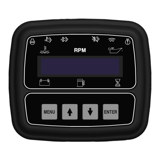
Engine Display & Control Panel
J1939 iT4 Engines
Part Number: C4F-100
Revision: 1.1
______________________________________________________________________________________________________________________________________
Copyright Controls, Inc.
P.O. Box 368 • Sharon Center, OH 44274
Phone 330.239.4345 • Fax 330.239.2845 • www.controlsinc.com
Advertisement
Table of Contents

Related Manuals for Controls J1939 iT4

Summary of Contents for Controls J1939 iT4
- Page 1 Product Manual Engine Display & Control Panel J1939 iT4 Engines Part Number: C4F-100 Revision: 1.1 ______________________________________________________________________________________________________________________________________ Copyright Controls, Inc. P.O. Box 368 • Sharon Center, OH 44274 Phone 330.239.4345 • Fax 330.239.2845 • www.controlsinc.com...
-
Page 2: Table Of Contents
CONTROLS, INCORPORATED C O N T R O L S Y S T E M S & S O L U T I O N S TABLE OF CONTENTS CONTROL PANEL SETTINGS……. ………………………………………………………………………….…….……….…………... PRIOR TO STARTING ENGINE MANUAL OPERATION SETTINGS OVERVIEW OPERATION SETTINGS………..…... -
Page 3: Control Panel Settings
CONTROLS, INCORPORATED C O N T R O L S Y S T E M S & S O L U T I O N S MODULE OPERATION The modules are designed to be integrated into a panel that assumes a traditional key switch is used. -
Page 4: Manual Operation Settings Overview
CONTROLS, INCORPORATED C O N T R O L S Y S T E M S & S O L U T I O N S Manual Operation Settings The following bolded settings are required for manual (and automatic) operation in the Throttle Configuration menu. -
Page 5: Operation Settings
CONTROLS, INCORPORATED C O N T R O L S Y S T E M S & S O L U T I O N S OPERATION SETTINGS Manual Throttle Control With the key in the RUN position, the panel operates manually by pressing the up and down buttons. -
Page 6: Module Connectors
CONTROLS, INCORPORATED C O N T R O L S Y S T E M S & S O L U T I O N S MODULE CONNECTORS Primary Connector Secondary Connector 14 Pin 23 Pin - 5 -... - Page 7 CONTROLS, INCORPORATED C O N T R O L S Y S T E M S & S O L U T I O N S Primary Connector (14 Pin) Function Function Relay #2 -ECU Signal J1939 Low Relay #1 NO...
-
Page 8: Engine Alarms, Codes And Messages
CONTROLS, INCORPORATED C O N T R O L S Y S T E M S & S O L U T I O N S ENGINE ALARMS, CODES AND MESSAGES Engine ECU Alarm/De-Rate/Shut Downs It is important to understand panel operation with respect to engine safety protections, alarms, and fault codes. -
Page 9: Active And Stored Engine Ecu Codes
CONTROLS, INCORPORATED C O N T R O L S Y S T E M S & S O L U T I O N S Indicator Lamps The panel has six lamp indicators. Regen Regen Active Inhibit Heat Lamp... -
Page 10: Control Panel Specific Alarms And Shut Downs
CONTROLS, INCORPORATED C O N T R O L S Y S T E M S & S O L U T I O N S CONTROL PANEL SPECIFIC ALARMS AND SHUT DOWNS The panel has its own engine safety alarms and shut downs that can be enabled. These alarms and shut downs are managed by the control panel independent from the engine ECU. -
Page 11: Control Panel Analog And Digital Inputs
CONTROLS, INCORPORATED C O N T R O L S Y S T E M S & S O L U T I O N S CONTROL PANEL ANALOG AND DIGITAL INPUTS The panel has one analog input and up to nine digital inputs available to monitor other components, senders or signals. - Page 12 CONTROLS, INCORPORATED C O N T R O L S Y S T E M S & S O L U T I O N S Analog 1 Function Options 1) Fuel Level S-W – Fuel amount, in percentage, can be measured and displayed on the C3 module using a standard Stewart Warner scale sender of 240 ohms –...
- Page 13 CONTROLS, INCORPORATED C O N T R O L S Y S T E M S & S O L U T I O N S Digital Function Activation 1) Off / Always / Run – Describes when the parameter will be monitored for alarm conditions.
-
Page 14: Control Panel Relay Outputs
CONTROLS, INCORPORATED C O N T R O L S Y S T E M S & S O L U T I O N S CONTROL PANEL RELAY OUTPUTS A total of eight relays can be assigned for different uses depending on application to provide relay output signals to external devices such as horns, sirens, PLC’s or SCADA systems. - Page 15 CONTROLS, INCORPORATED C O N T R O L S Y S T E M S & S O L U T I O N S g. Engine Run – Relay will be active when engine RPM is greater than 600. Typically used to drive an auxiliary circuit such as louvers or send a signal to a monitoring station.
-
Page 16: Menu System
CONTROLS, INCORPORATED C O N T R O L S Y S T E M S & S O L U T I O N S MENU SYSTEM To Enter Menu System Hold MENU button and press ENTER button. Menu Navigation Press MENU button to scroll menu options. - Page 17 CONTROLS, INCORPORATED C O N T R O L S Y S T E M S & S O L U T I O N S Main Menus Main Menus Sub Menus Emissions Parameters Regen Options (Auto, Inhibit, Request) DPF Soot Load % View...
- Page 18 CONTROLS, INCORPORATED C O N T R O L S Y S T E M S & S O L U T I O N S Input Configuration Analog 1 Function (Default = None) Digital Input 1 Setup – (NO/NC, Action, Message, When Active, Delay)
- Page 19 CONTROLS, INCORPORATED C O N T R O L S Y S T E M S & S O L U T I O N S Module Configuration English/Metric Selection (Default = English) Hour Meter Source (Default = Engine ECU)
-
Page 20: Emissions Monitoring
CONTROLS, INCORPORATED C O N T R O L S Y S T E M S & S O L U T I O N S EMISSIONS MONITORING Emissions Information The panel provides lamp indications, display messages and other emission related information. - Page 21 CONTROLS, INCORPORATED C O N T R O L S Y S T E M S & S O L U T I O N S Regeneration The regeneration process is controlled by the engine ECU. The engine ECU monitors emissions parameters such as soot level and ash level.
-
Page 22: Standard Regeneration
CONTROLS, INCORPORATED C O N T R O L S Y S T E M S & S O L U T I O N S DPF Lamp (Blinking) At the most severe level, the DPF lamp blinks and the red engine alarm lamp illuminates. - Page 23 CONTROLS, INCORPORATED C O N T R O L S Y S T E M S & S O L U T I O N S Regen Active Lamp Lamp The regeneration active lamp illuminates during the regeneration process. The DFP lamp stays illuminated until the engine ECU determines that a regeneration is no longer required.
- Page 24 CONTROLS, INCORPORATED C O N T R O L S Y S T E M S & S O L U T I O N S Service Regen Level The most severe level is the service regen level. At this level, the DFP lamp is blinking and the red alarm lamp illuminates.
Need help?
Do you have a question about the J1939 iT4 and is the answer not in the manual?
Questions and answers