Advertisement
Quick Links
Advertisement

Subscribe to Our Youtube Channel
Summary of Contents for Electro-Tech systems 5112
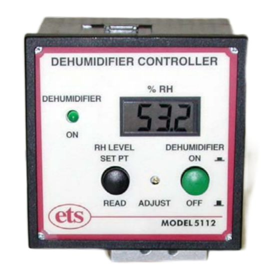
- Page 1 DEHUMIDIFIER CONTROLLER MODEL 5112 Operating Instructions 11/28/05...
- Page 2 115/230 VAC, 3 Amp output is able to control dehumidification systems that operate within the limits of the controller's power handling capacity. The Model 5112 is capable of is capable of measuring relative humidity over the entire 0 to 100% range. The standard sensor supplied with the Controller has a response time satisfactory for maintaining long-term humidity stability.
- Page 3 0 to 100% R.H. A separate pushbutton switch controls the Dehumidify function. When the DEHUMIDIFIER switch is in the OFF position, the Model 5112 operates as a precision electronic hygrometer. The system Power switch and the controlled North American 3-prong grounded outlet are located on the rear panel.
-
Page 4: System Description
pump circulating the test chamber air through the desiccator or injecting dry gas through a solenoid valve. For the desiccator system the desiccant absorbs moisture, thereby lowering the humidity level inside the chamber. When the set point humidity level is reached, the Controller turns off the pump. The pump will then cycle on and off automatically as required by the Controller to maintain the desired humidity level. - Page 5 3.1.2 Controls 3.1.2.1 READ RH/SET RH This is the black momentary pushbutton switch. In the normal (out) position, the measured humidity level is displayed on the LCD meter. When depressed to the SET RH position, the humidity level set point is displayed. Upon release, the switch returns to the READ RH position.
- Page 6 3.2.1 POWER The Power switch, Fuse and AC line cord are separate components that control the power input to the Model 5112 Controller. The AC line cord is a standard North American 3-prong grounded type, 8” (2.5m). The Model 5112 contains a universal power supply that operates from 90-260VAC, 50/60Hz.
-
Page 7: Installation
4.0 INSTALLATION AND OPERATION Initial Check Out Unpack the Control Unit and Sensor and inspect for visible damage. If no damage is observed then proceed to check out the system as follows: NOTE All equipment being used with the Controller must match the voltage selected. - Page 8 (92x92mm cutout) using the optional mounting clips. Plug the Dehumidifier into the AC Output receptacle. Plug the Controller line cord into the appropriate power outlet (115 or 230 VAC). The Model 5112 Dehumidifier Controller is now ready for operation.
- Page 9 ±3% RH. 4.3.4 Using the Model 5112 as a Humidity Indicator Only If the Model 5112 Controller is to be used as a humidity indicator only (no humidity control), place the DEHUMIDIFIER switch to OFF. The system now becomes a humidity level meter (hygrometer) only.
- Page 10 As an alternative, certified calibration salt solution cells can also be used. The Model 5112 is calibrated by comparing the relative humidity reading with the reading of a known calibrated reference. The reference sensor should be placed next to the Model 5112 sensor and allowed to stabilize for at least 30 minutes before making any adjustments to the sensor electronics.
-
Page 11: Troubleshooting
6.0 TROUBLESHOOTING The Model 5112 is all solid state and should provide many years of trouble-free service. If a problem with the system is suspected, it is recommended that the fault be initially isolated to either the Sensor or the Control unit. - Page 12 To gain access to the PC board it will be necessary to first remove the front panel. Snap off the front bezel as shown in Figure 6.0-1 and remove the 4 screws. It may also be necessary to remove the rear panel to provide enough slack in the internal wiring to reach the fuse or U1.
-
Page 13: Warranty
7.0 WARRANTY Electro-Tech Systems, Inc. warrants its equipment, accessories and parts of its manufacture to be and remain free from defects in material and workmanship for a period of one (1) year from date of invoice and will, at the discretion of Seller, either replace or repair without charge, F.O.B.
Need help?
Do you have a question about the 5112 and is the answer not in the manual?
Questions and answers