
Subscribe to Our Youtube Channel
Related Manuals for Ampac EvacU Elite

Summary of Contents for Ampac EvacU Elite
- Page 1 EvacU Elite Emergency Warning & Intercom System (EWIS) Install, Commission and User Manual MAN3137-2...
-
Page 2: Table Of Contents
Table of Contents Page No Certification Information ................1 Purpose ......................2 Scope ........................2 References ......................2 2.2.1 EvacU ELITE System Manuals: .............. 2 2.2.2 Australian Standards ................2 System overview ..................3 General ....................... 3 Access levels ..................... 3 Emergency warning control and indicating equipment ........ - Page 3 5.3.9 Test ....................31 EWS Operation ....................31 5.4.1 General ....................31 5.4.2 Live Speech ..................31 5.4.3 Automatic Operation ................. 31 5.4.4 Manual Operation ................32 5.4.5 Disabling Emergency Zones ............. 33 5.4.6 Activating the Test Tone ..............35 5.4.7 Test Condition ...................
- Page 4 Connecting to the EvacU ELITE ..............79 General ......................79 Distribution CPU ....................79 8.2.1 Connections ..................79 8.2.2 Indications ..................80 Multi-purpose output card (MOC) ..............80 8.3.1 Connections ..................80 8.3.2 Indicators ................... 82 8.3.3 Field wiring ..................82 Multi-purpose interface card (MIC) ..............
- Page 5 Definitions ....................121...
- Page 6 Table of Figures Page No Figure 4-1 - EvacU ELITE and FireFinder PLUS 24U COMBO unit - external view ........6 Figure 4-2 - All-purpose back plane board ..................8 Figure 4-3 Front view of the universal rack ..................8 Figure 4-4 Side view of the universal rack ..................
- Page 7 Figure 6-29 Graphical user interface status ..................57 Figure 6-30 Power supply status screen ..................58 Figure 6-31 Power supply status ...................... 58 Figure 6-32 Power supply module status ..................58 Figure 6-33 Battery status ........................ 59 Figure 7-1 24U Cabinet – Front and side view ................. 73 Figure 7-2 24U Cabinet - Rear view showing mounting points ............
-
Page 8: Certification Information
EVACU ELITE INSTALLATION, COMMISSIONING AND USER MANUAL Certification Information EVACU ELITE EMERGENCY WARNING AND INTERCOMMUNICATION SYSTEM MANUFACTURED BY: AMPAC Pty Ltd. 7 LEDGAR RD BALCATTA WA 6017 WESTERN AUSTRALIA PH: 61-8-9201 6100 FAX: 61-8-9201 6101 www.ampac.net CONFORMS TO: AS 4428.16 AS 4428.4... -
Page 9: Purpose
The EvacU ELITE also complies with IEC 62368-1 Audio / video, information and communication technology equipment – Part 1 Safety requirements. IEC 62368 has replaced IEC 60950 as the safety standard is some overseas countries, and as EvacU ELITE will be sold overseas, approval to both safety standards is required. -
Page 10: System Overview
EVACU ELITE INSTALLATION, COMMISSIONING AND USER MANUAL System overview 3.1 General The EvacU ELITE has been designed to meet the requirements of an Emergency Warning Control and Indicating Equipment (EWCIE) and Emergency Intercom Control and Indicating Equipment (EICIE), conforming to AS 4428.16 and AS 4428.4. -
Page 11: Emergency Warning Control And Indicating Equipment
EVACU ELITE INSTALLATION, COMMISSIONING AND USER MANUAL 3.3 Emergency warning control and indicating equipment The product standard for EWCIE (AS 4428.16) details three grades of equipment. The following table details the mandatory, optional and excluded functionality for each grade. The EvacU conforms to Grade 1. -
Page 12: Emergency Intercom Control And Indicating Equipment
EVACU ELITE INSTALLATION, COMMISSIONING AND USER MANUAL O = optional function X = shall not be provided Option Included in the EvacU ELITE Option not included in the EvacU ELITE 3.4 Emergency intercom control and indicating equipment The following optional clauses of AS 4428.4 are supported by the EvacU Elite Clause 8.8... -
Page 13: System Description
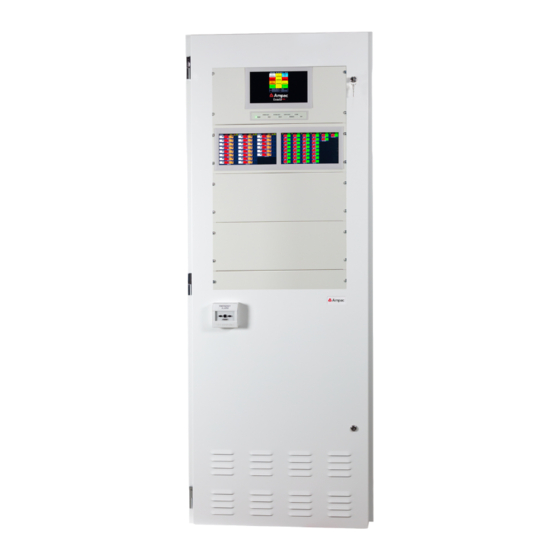
PLUS 24U COMBO unit - external view Figure 4-1 above shows an external view of the EvacU ELITE and FireFinder PLUS. The cabinet size is 24U. Cabinet has been designed so all controls are 750mm from floor level. Page 6... -
Page 14: System Components
EVACU ELITE INSTALLATION, COMMISSIONING AND USER MANUAL Figure 4-2 Evacu ELITE and FireFinder PLUS COMBO unit internal view Figure 4-2 shows the internal view of the EvacU ELITE and FireFinder PLUS . The cabinet size is 24U. This configuration shows a single universal rack frame with a number of cards fitted, scalable power supply and single graphical user interface fitted. -
Page 15: Figure 4-2 - All-Purpose Back Plane Board
EVACU ELITE INSTALLATION, COMMISSIONING AND USER MANUAL Each rack has a dedicated DCPU slot (slot 0) and 16 slots for cards. The LPA and HPA each require 2 slots. The NIC when fitted occupies 1 slot adjacent to the DCPU. -
Page 16: Power Supply
(depends on the site-specific data) Each power supply module consists of an off the shelf Meanwell power supply and an Ampac designed power control card. -
Page 17: Figure 4-5 Power Supply Module
EVACU ELITE INSTALLATION, COMMISSIONING AND USER MANUAL Figure 4-5 Power supply module 4.2.2.2 PSU labelling Following labelling is used on the primary power supply module Figure 4-6 Primary power supply labelling General Status LED Indication Condition No power Green steady Normal –... -
Page 18: Figure 4-7 Secondary Power Supply Labelling
EVACU ELITE INSTALLATION, COMMISSIONING AND USER MANUAL Following labelling is used on the secondary power supply module Figure 4-7 Secondary power supply labelling General Status LED Indication Condition No power Green steady Normal – mains available Green flashing Mains is off – running from the standby power source Yellow flashing Fault –... -
Page 19: Figure 4-8 Power Supply Distribution Board
EVACU ELITE INSTALLATION, COMMISSIONING AND USER MANUAL Figure 4-8 Power supply distribution board The Power distribution board has termination for the primary power source (mains) and the standby power source (batteries). CN1 connects to the first all-purpose backplane. CN2 connects to the primary power supply module, and CN3 and CN4 connect to the secondary power supply modules. -
Page 20: Figure 4-9 Three Power Supply Modules Connected To The Power Supply Distribution Board
EVACU ELITE INSTALLATION, COMMISSIONING AND USER MANUAL Figure 4-9 Three power supply modules connected to the power supply distribution board Figure 4-10 Power supply - showing the primary power supply module Page 13... -
Page 21: Graphical User Interface
EVACU ELITE INSTALLATION, COMMISSIONING AND USER MANUAL Fig 4-10 shows the power supply and universal rack with cards fitted. The primary and standby power source wiring is visible. The wiring for the air circulating fans and battery temperature sensor is visible. -
Page 22: Universal Rack Cards
EVACU ELITE INSTALLATION, COMMISSIONING AND USER MANUAL Figure 4-12 Graphical user interface The touchscreen is a 9-inch TFT LCD 800 x 480 with LED backlighting and resistive touch screen. USB Host Used to update firmware and configuration files by USB Flash drive... -
Page 23: Figure 4-13 Distribution Cpu
Provides eight single ended supervised outputs, suitable for driving alarm warning devices such as strobes (VADs) or vibrating pads. Each pair of outputs can be configured as a reverse polarity output, suitable for driving Ampac alert/evac strobes. Refer to section 8.3 for suitable alert and evac strobes. -
Page 24: Figure 4-15 Multi-Purpose Interface Card
6 amps per card. Selectable EOL. Output voltage range 12 to 28VDC. 4.2.4.3 Multi-purpose interface card Occupies one slot Provides eight supervised inputs, two relay outputs and a high-level interface to the Ampac FireFinder PLUS Add On Bus. Figure 4-15 Multi-purpose interface card... -
Page 25: Figure 4-16 Dual 25-Watt Amplifier
EVACU ELITE INSTALLATION, COMMISSIONING AND USER MANUAL Figure 4-16 Dual 25-watt amplifier Max Drive Voltage 100V rms @ full load Distortion <=0.1%@ 25Watt x2 Frequency Response 400 Hz to 10kHz +/- 1dB w.r.t. 1kHz (AS 4428.16) 200 Hz to 12kHz +/- 3dB w.r.t. 1kHz >=70db... -
Page 26: Figure 4-18 150-Way Amplifier
EVACU ELITE INSTALLATION, COMMISSIONING AND USER MANUAL 4.2.4.6 150Watt Amplifier Card Occupies two slots Provides one 150watt amplifier with an integrated 4way audio splitter. Each audio output is individually switchable and DC supervised with a nominal 47kΩ. Audio output #1 is rated at 150watt, and the remaining audio outputs (2, 3 and 4) are rated at 75watt max each. -
Page 27: Figure 4-19 Quad Radial Eis Line Card
Inputs for Ampac EvacU WIP handsets (polarity insensitive). Up to 2 ELITE 3 and 4 Ampac MCPs can be connected to each handset. Cabling size recommended is 1.5mm 2 Core,max length 1 km, line impedance 600Ω, bandwidth 3K4 Hz. 4.2.4.8 Dual Loop EIS line card... -
Page 28: Networking
EVACU ELITE INSTALLATION, COMMISSIONING AND USER MANUAL 4.2.5 Networking 4.2.5.1 General The EvacU ELITE is capable of being arranged to function stand-alone, networked or a distributed configuration. For a networked or distributed configuration, a Network Interface Card (NIC) is required at each node. -
Page 29: Figure 4-22 Detail On Fitting The Sfp Module To The Nic For Vdsl Connection (2 Core Copper)
EVACU ELITE INSTALLATION, COMMISSIONING AND USER MANUAL Figure 4-22 Detail on fitting the SFP module to the NIC for VDSL Connection (2 core copper) To set the node address – refer to section 8.10.3 For networking wiring examples – refer to section 8.10... -
Page 30: Ewcie And Eicie Operation
EVACU ELITE INSTALLATION, COMMISSIONING AND USER MANUAL EWCIE and EICIE Operation 5.1 Front Control Panel 5.1.1 General The Front Control Panel contains all the system wide controls and indicators for the EWCIE and EICIE functionality, and individual controls and indicators for the emergency warning zones (EWCIE) and WIP handsets (EICIE) according to the site-specific data (SSD). -
Page 31: Test Condition Control (Ews)
EVACU ELITE INSTALLATION, COMMISSIONING AND USER MANUAL While in the manual mode, emergency warning signals can be manually broadcast to selected emergency zone by activating the all call or individual emergency zone manual controls (refer to section 5.1.12) 5.1.3.1 Automatic mode control and indicator The green indicator is illuminated steady, when the EWCIE is in the automatic mode. -
Page 32: Reset Control (Ews)
EVACU ELITE INSTALLATION, COMMISSIONING AND USER MANUAL The SILENCE WARNING has 3 options: Silence (extinguish) the visual warning • Silence the audible warning • Silence the audible and visual • The yellow indicator is illuminated steady if the audible or visual outputs have been silenced. -
Page 33: Silence Buzzer Control (Ews And Eis)
EVACU ELITE INSTALLATION, COMMISSIONING AND USER MANUAL 5.1.7.3 All evac control and indicator The red indicator is illuminated steady when the EWCIE is in All Evac and all emergency zones are broadcasting the evacuation warning signal. To place the EWCIE in All Evac, activate the ALL-EVAC control at access level 2 or higher. -
Page 34: All Call Control And Indicator (Eis)
EVACU ELITE INSTALLATION, COMMISSIONING AND USER MANUAL 5.1.10 All call control and indicator (EIS) The red indicator is illuminated steady when an All Call has been instigated. An All Call will initiate a call to broadcast to all WIP handsets. -
Page 35: Individual Eis Controls And Indicators
EVACU ELITE INSTALLATION, COMMISSIONING AND USER MANUAL • ALM – illuminated when there is an alarm signal present in the emergency zone FLT – illuminated when there is a fault with the emergency zone and associated • transmission path •... -
Page 36: Remote Control Indicator
EVACU ELITE INSTALLATION, COMMISSIONING AND USER MANUAL Each WIP handset in the EIS has its own controls and indicators. Refer to Figure 5-6 and 5-7 below Figure 5-6 WIP handset with controls highlighted There are two controls associated with each WIP CALL –... -
Page 37: Talk Indicator
EVACU ELITE INSTALLATION, COMMISSIONING AND USER MANUAL 5.1.16 Talk indicator The TALK indicator is illuminated steady when the Audio channel is open, in response to the PTT control of the emergency microphone being activated. 5.1.17 EICIE in control indicator If there are multiple EICIEs networked in the EIS, the EICIE in CTRL... -
Page 38: Earth Fault
EVACU ELITE INSTALLATION, COMMISSIONING AND USER MANUAL The indicator is extinguished when the EWCIE is in the emergency warning condition. Refer to section 5.4.3.1 5.3.6 Earth Fault Earth Fault – Earth fault condition on the EWCIE or EICIE 5.3.7 Disabled Disabled –... -
Page 39: Manual Operation
EVACU ELITE INSTALLATION, COMMISSIONING AND USER MANUAL When an alarm signal is recognised, the EWS will respond by entering the emergency warning condition and broadcasting emergency warning signals to the designated emergency zones in a pre- configured sequence, referred to as phasing or sequencing. In addition to broadcasting the emergency... -
Page 40: Disabling Emergency Zones
EVACU ELITE INSTALLATION, COMMISSIONING AND USER MANUAL When the EWS consists of multiple EWCIEs networked together, only one EWCIE can be in control at any one time, and the REMOTE CTRL indicator is illuminated at All EWCIE, except the EWCIE that is in control. - Page 41 EVACU ELITE INSTALLATION, COMMISSIONING AND USER MANUAL To Disable Zone 1, activate the control on the Zones screen. On the Zone Settings screen, activate control Zone setting screen updated to show the disable 5.4.5.2 To view the disabled emergency zones...
-
Page 42: Activating The Test Tone
EVACU ELITE INSTALLATION, COMMISSIONING AND USER MANUAL Activate the MENU control Activate the DISABLE control Screen display the list of disabled zones, and details the date and time when the zone was disabled. 5.4.6 Activating the Test Tone A test tone can be activated in an emergency zone. - Page 43 EVACU ELITE INSTALLATION, COMMISSIONING AND USER MANUAL Activate the MENU control Activate the ZONE control To activate the test tone for zone 1, activate the control on the Zones screen. Page 36...
-
Page 44: Test Condition
EVACU ELITE INSTALLATION, COMMISSIONING AND USER MANUAL On the Zone Settings screen, activate control to turn the test tone on and off. The volume of the test tone is adjusted by the associated slider control. 5.4.7 Test Condition There is a facility to test all emergency zones. Refer to section 5.1.4 When in the test condition, indications are unaffected. -
Page 45: Eis Operation
EVACU ELITE INSTALLATION, COMMISSIONING AND USER MANUAL 5.5 EIS Operation 5.5.1 General The purpose of the Emergency Intercom System is to provide a dedicated communications system between the Main Fire Warden (usually situated in the fire control room) and the Floor Wardens, situated at the Warden Intercom Points (WIP), which are normally located on each floor of a building near the egress points. -
Page 46: Establishing A Multi-Party Conference Call
EVACU ELITE INSTALLATION, COMMISSIONING AND USER MANUAL Ring tone will be broadcast in the ear piece of the WIP handset. The call indicator corresponding to the WIP handset that is off hook with flash at the EICIE. The panel buzzer at the EICIE will pulse (at the same cadence as the ring tone) To establish the call, remove the handset from the cradle at the EICIE. -
Page 47: Networked Eicie
EVACU ELITE INSTALLATION, COMMISSIONING AND USER MANUAL Activate the All-call control. The red indicator illuminates steady All the Call indicators flash As the WIP handsets are taken off hook the associated Call indicator goes steady to indicate the half duplex call the WIP handset has been established. -
Page 48: Remote Paging Console
EVACU ELITE INSTALLATION, COMMISSIONING AND USER MANUAL 5.6 Remote Paging Console Currently not available. Page 41... -
Page 49: Menu System
EVACU ELITE INSTALLATION, COMMISSIONING AND USER MANUAL Menu System Activating the Menu control at access level 2 will display the main menu screen. Refer to figure 6-1. The main menu screen Figure 6-1 Main menu screen 6.1 General The following controls are available on all screens Help Button - Home screen –... -
Page 50: Nodes
EVACU ELITE INSTALLATION, COMMISSIONING AND USER MANUAL When a control / facility requiring access level 3 is attempted (and the EvacU is at access level 2 – outer ELITE door open), the following screen is displayed, prompting the user to enter their UserID and password. - Page 51 EVACU ELITE INSTALLATION, COMMISSIONING AND USER MANUAL Nodes Screen Shows a list of nodes configured in the system. If there are any faults on a node, there will be in the column. column shows the status of the network. If the node reference has the...
-
Page 52: Distribution Cpu Card
EVACU ELITE INSTALLATION, COMMISSIONING AND USER MANUAL Dual 25-watt amplifier card, located in rack 1, slots 5 and 6. To view the status of this card, select the Dual 25-watt amplifier card Icon 50-watt amplifier card, located in rack 1, slots 7 and 8. A second card if fitted in slots 9 and 10. -
Page 53: Network Interface Card
EVACU ELITE INSTALLATION, COMMISSIONING AND USER MANUAL Figure 6-4 Distribution CPU card status Above is the module type “CPU”, location – Node 1, Rack 1, Slot 0, Software version 01.01.08, hardware version 00.01.000 and status is Normal. Figure 6-5 Input status There is a record for each of the 4 inputs, showing the allocated zone, description, state, status and action. -
Page 54: Multi-Purpose Interface Card
EVACU ELITE INSTALLATION, COMMISSIONING AND USER MANUAL Figure 6-7 Network interface card status screen The following explains the content of the screen Display the previous module in the node Display the next module in the node Figure 6-8 Network interface card status Above is the module type “NIC PRIMARY”, the primary denotes that this NIC is the current primary of the... -
Page 55: Figure 6-9 Multi-Purpose Interface Card Status Screen
EVACU ELITE INSTALLATION, COMMISSIONING AND USER MANUAL Figure 6-9 Multi-purpose interface card status screen The following explains the content of the screen Display the previous module in the node Display the next module in the node Display the virtual (HLI based) inputs – inputs are currently displayed as the icon is highlighted. -
Page 56: Multi-Purpose Output Card
EVACU ELITE INSTALLATION, COMMISSIONING AND USER MANUAL Figure 6-11 Multi-purpose interface card showing the outputs There is a record for each of the 2 outputs, showing the output type, allocated zone number, descriptor, state and status. 6.3.4 Multi-purpose output card The multi-purpose output card has 8 outputs, and outputs can be formed into pairs. -
Page 57: Quad Radial Eis Line Card
EVACU ELITE INSTALLATION, COMMISSIONING AND USER MANUAL In the above screen: • Output 1 and 2 are a pair – creating a polarity reversal output (2 wire dual strobes) • Output 3 and 4 are a pair Output 5 single output •... -
Page 58: Figure 6-15 Quad Radial Eis Line Card Status Screen
EVACU ELITE INSTALLATION, COMMISSIONING AND USER MANUAL Figure 6-15 Quad radial EIS line card status screen The following explains the content of the screen Display the previous module in the node Display the next module in the node Display the status of the handsets – handsets are currently displayed as the icon is highlighted Press to display the inputs. -
Page 59: Dual Loop Eis Line Card
EVACU ELITE INSTALLATION, COMMISSIONING AND USER MANUAL Figure 6-18 Quad radial EIS card status showing the inputs There are four inputs (one associated with each handset), and the inputs are digital, assigned to a zone, have a description, state and status. -
Page 60: Figure 6-20 Dual Loop Eis Line Card Status
EVACU ELITE INSTALLATION, COMMISSIONING AND USER MANUAL The following explains the content of the screen Display the previous module in the node Display the next module in the node Display the status of the handsets – handsets are currently displayed as the icon is highlighted Press to display the inputs. -
Page 61: Dual 25-Watt Amplifier Card
EVACU ELITE INSTALLATION, COMMISSIONING AND USER MANUAL Above is status the inputs associated with the WIP handsets – since the icon is highlighted. With the first entry: Location is loop 1 (of 2), address is 01 (of 20) – on the loop •... -
Page 62: Figure 6-24 Dual 25-Watt Amplifier Card Status Screen
EVACU ELITE INSTALLATION, COMMISSIONING AND USER MANUAL Figure 6-24 Dual 25-watt amplifier card status screen The following explains the content of the screen Display the previous module in the node Display the next module in the node Figure 6-25 Dual 25-watt amplifier card status Above is the module type “25W/25W Amp”, location –... -
Page 63: 50Watt Amplifier Card
EVACU ELITE INSTALLATION, COMMISSIONING AND USER MANUAL 6.3.8 50Watt amplifier card The 50-watt amplifier card supports 1x50 watt amplifier, refer to section 4.2.4.5. The status screen for the 50- watt amplifier card shows the modules status and the status of the amplifier as follows: Figure 6-27 50-watt amplifier card status screen The display is identical to the Dual 25-watt amplifier card, refer to section 6.3.7 –... -
Page 64: Power Supply
EVACU ELITE INSTALLATION, COMMISSIONING AND USER MANUAL Figure 6-28 Graphical user interface status screen The following explains the content of the screen Display the previous module in the node Display the next module in the node Figure 6-29 Graphical user interface status From above is the module type “GUI PRIMARY”, location –... -
Page 65: Figure 6-30 Power Supply Status Screen
EVACU ELITE INSTALLATION, COMMISSIONING AND USER MANUAL Figure 6-30 Power supply status screen The following explains the content of the screen Display the previous module in the node Display the next module in the node Figure 6-31 Power supply status Figure 6-31 details the overall power status of the cabinet. -
Page 66: Zones
EVACU ELITE INSTALLATION, COMMISSIONING AND USER MANUAL Figure 6-33 Battery status Figure 6-33 details the status of the connected batteries, detailing size, voltage, temperature, charge level, charge current and lead resistance. 6.4 Zones To access the Zones screen, the following controls are activated... -
Page 67: Wips
EVACU ELITE INSTALLATION, COMMISSIONING AND USER MANUAL control allows the zone descriptor to be changed. There are two zone descriptors – a short and long. The short descriptor is displayed above the Status and Test Tone fields and is used in the individual EWS controls and indicators. Refer to section 5.1.12. -
Page 68: Alarms
EVACU ELITE INSTALLATION, COMMISSIONING AND USER MANUAL 6.6 Alarms Menu control Alarm control – only if there is at least one alarm present. Control shows 1 alarm condition Alarm Screen Shows a list of alarms. column zones the zone number in alarm... - Page 69 EVACU ELITE INSTALLATION, COMMISSIONING AND USER MANUAL Zone 2 Fault Detail Shows the detail for zone 2, and the audio output is in fault. Zone 3 Fault Detail Shows the detail for zone 3, and the audio output is in fault.
-
Page 70: Disables
EVACU ELITE INSTALLATION, COMMISSIONING AND USER MANUAL Node 1 Screen shows there is a fault on the 50watt amplifier in slot 7/8 Amplifier status screen From the status screen – the status of the module is missing 6.8 Disables Menu control Disables control –... -
Page 71: Date And Time
EVACU ELITE INSTALLATION, COMMISSIONING AND USER MANUAL Log control Logs Screen Shows a list of events that have occurred in the system. control clears the logs. Clearing the logs Prompted to confirm clearing the logs 6.10 Date and Time To set the date and time, the following controls are activated... - Page 72 EVACU ELITE INSTALLATION, COMMISSIONING AND USER MANUAL To set the daylight-saving start/end time, select the control To set the daylight-saving start/end date, select the control Setting the Time Setting the Date Setting daylight saving start or end time Page 65...
-
Page 73: Sequencing
EVACU ELITE INSTALLATION, COMMISSIONING AND USER MANUAL Setting the daylight-saving start or end day 6.11 Sequencing To edit the sequencing, refer to the following steps Menu control Sequencing control (requires access level 3) Sequence Screen Shows the sequence type, the number of zones, delay to alert and delay to evac. - Page 74 EVACU ELITE INSTALLATION, COMMISSIONING AND USER MANUAL Refer to the Sequencing Table in this section (6.11) for further detail on the sequence. Number of zones screen To set/change the number of zones – activate the control. controls step thru the number of...
-
Page 75: Zone Delay Off/On
EVACU ELITE INSTALLATION, COMMISSIONING AND USER MANUAL accepts the displayed delay to evac. The sequencing controls determines how the EWS reacts to an alarm signal. Alarm signals can be programmed to generate an alert event type or an evacuate event type (in the context of... -
Page 76: Access Level
EVACU ELITE INSTALLATION, COMMISSIONING AND USER MANUAL Refer to section 5.4.3.1 for information on delays On the main menu screen, the following is displayed Menu control Menu Screen The Zone Delay control is provided to switch delays On and Off. Delays are programmed and currently switched On –... -
Page 77: Fad Retrigger
EVACU ELITE INSTALLATION, COMMISSIONING AND USER MANUAL Menu Screen The Access Level control displays the current access level. Activating the control – will prompt for a new User ID and password – see section 6.2. If a level 3 user ID and password is... - Page 78 EVACU ELITE INSTALLATION, COMMISSIONING AND USER MANUAL Page 71...
-
Page 79: Installation
Ensure all wiring is secure, and all connections are secure, and that all fixings and earth studs are tight. If any damage has occurred, please contact Ampac in writing within 14 days, as per Ampac’s terms of sale. 7.2 Ant-static precautions... -
Page 80: Figure 7-1 24U Cabinet - Front And Side View
EVACU ELITE INSTALLATION, COMMISSIONING AND USER MANUAL Figure 7-1 24U Cabinet – Front and side view Page 73... -
Page 81: Figure 7-2 24U Cabinet - Rear View Showing Mounting Points
EVACU ELITE INSTALLATION, COMMISSIONING AND USER MANUAL Figure 7-2 24U Cabinet - Rear view showing mounting points Figure 7-3 24U Cabinet – Top view showing the gland plate and cable entry Page 74... -
Page 82: Figure 7-4 13U Cabinet - Front And Side View
EVACU ELITE INSTALLATION, COMMISSIONING AND USER MANUAL The 13U cabinet can be floor or wall mounted. Refer to figure 7.4, 7.5 ad 7.6 for cabinet dimensions, fixing points and cable entry. Figure 7-4 13U Cabinet - Front and side view... -
Page 83: Mains Termination
EVACU ELITE INSTALLATION, COMMISSIONING AND USER MANUAL Figure 7-6 13U Cabinet - Top view showing gland plate and cable entry 7.5 Mains termination The cabinets (13U and 24U) are fitted with a mains isolator and earth stud, located in the top left-hand corner of the cabinet. -
Page 84: Fitting Cards To The Universal Racks
EVACU ELITE INSTALLATION, COMMISSIONING AND USER MANUAL Figure 7-8 24U Cabinet showing the mains isolator, earth point and battery isolator 7.6 Fitting cards to the universal racks The plug-in cards for the universal rack (see section 4.2.4 and 4.2.5 for a detailed description of the cards) are packed separately to the cabinet. -
Page 85: Recommended Batteries
EVACU ELITE INSTALLATION, COMMISSIONING AND USER MANUAL The number of power supply modules fitted determines the rating of the battery isolator and the battery cabling size. The actual battery cable required does depend on the type of lugs on the batteries. -
Page 86: Connecting To The Evacu
EVACU ELITE INSTALLATION, COMMISSIONING AND USER MANUAL Connecting to the EvacU ELITE 8.1 General The mains termination is to the mains isolator located in the top left hand of the cabinet. All other terminations are accommodated to the front of the cards mounted in the universal racks. -
Page 87: Indications
EVACU ELITE INSTALLATION, COMMISSIONING AND USER MANUAL Relay 1 Double pole, single throw (1 x NO, 1 x NC, 2 x COM) Relay 2 & 3 Single pole, double throw (COM, NO, NC) Mini USB Not available for field connection... - Page 88 5, 6, 7 and 8 amps per output and 6 amps per card. Selectable EOL (3K3, 4K7, 10K). Output voltage range 12 to 28VDC. The outputs are typically used to drive VADs. Applicable Ampac Item number are: Ceiling Mount Item Number...
-
Page 89: Indicators
EVACU ELITE INSTALLATION, COMMISSIONING AND USER MANUAL 4107-1156 VXB-VW Wall mount red flash deep red body 4107-1157 VXB-VW Wall mount white flash shallow red body 4107-1158 VXB-VW Wall mount white flash deep red body 4107-1159 VXB-VW Wall mount amber flash shallow white body... -
Page 90: Figure 8-2 Mic Wiring - Standard
EVACU ELITE INSTALLATION, COMMISSIONING AND USER MANUAL Figure 8-2 MIC wiring - standard Page 83... -
Page 91: Figure 8-3 Mic Wiring - Voltage Reversal
EVACU ELITE INSTALLATION, COMMISSIONING AND USER MANUAL Figure 8-3 MIC wiring - voltage reversal Page 84... -
Page 92: Multi-Purpose Interface Card (Mic)
Relays 1 and 2 are general purpose The RJ45 connector is dedicated as the HLI to the FireFinder PLUS 8.4.2 Indications The Multi-purpose interface card has one status indicator, located adjacent to the Ampac FireFinder PLUS On bus connector Page 85... -
Page 93: Dual 25Watt Amplifier
EVACU ELITE INSTALLATION, COMMISSIONING AND USER MANUAL Status Indicator OFF: cards have no power or processor is fault FLASHING GREEN: board is operating, no faults FLASHING AMBER: board has a fault condition STEADY AMBER: receiving commands from the Distribution CPU 8.5 Dual 25Watt amplifier... - Page 94 400 Hz to 10kHz +/- 1dB w.r.t. 1kHz (AS 4428.16) 200 Hz to 12kHz +/- 3dB w.r.t. 1kHz >=70% Speaker Circuit DC, nominal 47kΩ Monitoring Applicable Ampac speaker item numbers Item Number Description 4113-1006 Ceiling speaker 4” 5W white 4113-1007 Ceiling speaker 4” 5W black 4113-1014 / 54 Ceiling speaker 4”...
-
Page 95: Indicators
EVACU ELITE INSTALLATION, COMMISSIONING AND USER MANUAL The following table details audio load, wire size and length of cable runs. Calculations are based on a 1 dB of loss (approx. 10V attenuation at the end of the cable run) Amp Size Load 1.0mm... -
Page 96: Figure 8-4 Dual 25Watt Amplifier Wiring
EVACU ELITE INSTALLATION, COMMISSIONING AND USER MANUAL Figure 8-4 Dual 25Watt amplifier wiring Refer to section 8.11 for detail on cable terminations and routings. Page 89... -
Page 97: 50Watt Amplifier
400 Hz to 10kHz +/- 1dB w.r.t. 1kHz (AS 4428.16) 200 Hz to 12kHz +/- 3dB w.r.t. 1kHz >=70% Speaker Circuit DC, nominal 47kΩ Monitoring Applicable Ampac speaker item numbers Item Number Description 4113-1006 Ceiling speaker 4” 5W white 4113-1007 Ceiling speaker 4” 5W black 4113-1014 / 54 Ceiling speaker 4”... -
Page 98: Indicators
EVACU ELITE INSTALLATION, COMMISSIONING AND USER MANUAL 4113-1035 Surface mount speaker 8” 15W black 4113-1074 Ceiling speaker 8” 15W low profile white 4113-1075 Ceiling speaker 8” 15W low profile black The following table details audio load, wire size and length of cable runs. -
Page 99: Field Wiring
EVACU ELITE INSTALLATION, COMMISSIONING AND USER MANUAL 8.6.3 Field wiring Figure 8-5 50Watt amplifier wiring Refer to section 8.11 for detail on cable terminations and routings. Page 92... -
Page 100: 150Watt Amplifier
EVACU ELITE INSTALLATION, COMMISSIONING AND USER MANUAL 8.7 150Watt amplifier OUTPUT 1 (-VE) OUTPUT 1 (+VE) OUTPUT 2 (-VE) OUTPUT 2 (+VE) OUTPUT 3 (-VE) OUTPUT 3 (+VE) OUTPUT 4 (-VE) OUTPUT 4 (+VE) Max Drive Voltage 100V rms @ full load Distortion <=0.3%@ 150Watt x1... -
Page 101: Field Wiring
EVACU ELITE INSTALLATION, COMMISSIONING AND USER MANUAL 8.7.1 Field wiring Figure 8-6 150Watt amplifier wiring Page 94... -
Page 102: Quad Radial Eis Line Card
Inputs for Ampac EvacU ELITE radial WIP handsets (polarity insensitive). Up to 3 and 4 2 Ampac MCPs can be connected to each handset. Cabling size recommended is 1.5mm 2 Core, Max length 1000m, line impedance 600Ω, bandwidth 3K4 Hz. -
Page 103: Indicators
EVACU ELITE INSTALLATION, COMMISSIONING AND USER MANUAL 8.8.2 Indicators The Quad radial EIS line card has one status indicator per handset output (4) and a general status indicator. See below Handset Status Indicators OFF: No fault, handset on hook FLASHING AMBER: Handset off hook... -
Page 104: Field Wiring
EVACU ELITE INSTALLATION, COMMISSIONING AND USER MANUAL 8.8.3 Field wiring Figure 8-7 Quad radial EIS wiring Page 97... -
Page 105: Dual Loop Eis Line Card
LOOP 2 IN + LOOP 2 IN - LOOP1/2 IN/OUT Inputs for Ampac EvacU Loop WIP handsets. Up to 2 Ampac MCPs can ELITE be connected to each handset. Max of 20 handsets per loop. Cabling size recommended 1.5mm 2 core UTP , Maximum loop length 1000m 8.9.2 Indicators... -
Page 106: Field Wiring - Use Of Ferrites On Each Loop Wip Card
EVACU ELITE INSTALLATION, COMMISSIONING AND USER MANUAL Loop Status Indicators AMBER: Fault – short, open, overload RED: power is present In redundant mode – only the Out port will be active under normal conditions General Status Indicator OFF: cards have no power or processor... -
Page 107: Figure 8-8 Dual Loop Eis Wiring
EVACU ELITE INSTALLATION, COMMISSIONING AND USER MANUAL Figure 8-8 Dual loop EIS wiring Page 100... -
Page 108: Network Interface Card
EVACU ELITE INSTALLATION, COMMISSIONING AND USER MANUAL 8.10 Network Interface Card 8.10.1 Connectors Following table details the field connections for the network interface card BGM 2 SHIELD BGM 1 SHIELD BGM 2 COLD BGM 1 COLD BGM 2 HOT BGM 1 HOT... -
Page 109: Setting The Node Address
EVACU ELITE INSTALLATION, COMMISSIONING AND USER MANUAL General Status Indicator OFF: cards have no power or processor is fault FLASHING GREEN: board is operating, no faults FLASHING AMBER: board has a fault condition STEADY AMBER: receiving commands from the Distribution CPU 8.10.3 Setting the node address... -
Page 110: Field Wiring
EVACU ELITE INSTALLATION, COMMISSIONING AND USER MANUAL 8.10.4 Field wiring Figure 8-9 Network wiring - side by side cabinets Page 103... -
Page 111: Figure 8-10 Network Wiring - 2 Core Copper
EVACU ELITE INSTALLATION, COMMISSIONING AND USER MANUAL Figure 8-10 Network wiring - 2 core copper Page 104... -
Page 112: Figure 8-11 Network Wiring - Single Mode, Single Fibre
EVACU ELITE INSTALLATION, COMMISSIONING AND USER MANUAL Figure 8-11 Network wiring – Single mode, single fibre Page 105... -
Page 113: Figure 8-12 Network Wiring - Single Mode, Dual Fibre
EVACU ELITE INSTALLATION, COMMISSIONING AND USER MANUAL Figure 8-12 Network wiring - Single mode, dual fibre Page 106... -
Page 114: Figure 8-13 Network Wiring - Multi Mode Dual Fibre
EVACU ELITE INSTALLATION, COMMISSIONING AND USER MANUAL Figure 8-13 Network wiring - Multi mode dual fibre Page 107... -
Page 115: Figure 8-14 Network Wiring - Mixed - Fibre
EVACU ELITE INSTALLATION, COMMISSIONING AND USER MANUAL Figure 8-14 Network wiring – Mixed - Fibre Page 108... -
Page 116: Figure 8-15 Networking Wiring - Mixed - Utp
EVACU ELITE INSTALLATION, COMMISSIONING AND USER MANUAL Figure 8-15 Networking wiring - Mixed - UTP Page 109... -
Page 117: Cable Terminations And Routing
EVACU ELITE INSTALLATION, COMMISSIONING AND USER MANUAL 8.11 Cable Terminations and Routing Both AS 4428.4 And AS 4428.16 require all internal cable terminations and cable routings to complete with the relevant clauses of AS/NZS3100 and AS/CA S009. To comply with the above, there must be 50mm separation between ELV and LV wiring. -
Page 118: Figure 8-17 Incorrect Speaker Wiring Termination
EVACU ELITE INSTALLATION, COMMISSIONING AND USER MANUAL Figure 8-17 Incorrect speaker wiring termination All speaker wiring should be routed away from the other ELV wiring Refer to figure 8-17 and 8-18 for guidelines on routing the field wiring into the cabinet. -
Page 119: Figure 8-18 Cable Routing - Left Hand Side
EVACU ELITE INSTALLATION, COMMISSIONING AND USER MANUAL Figure 8-18 Cable routing - left hand side Page 112... -
Page 120: Figure 8-19 Cable Routing - Right Hand Side
EVACU ELITE INSTALLATION, COMMISSIONING AND USER MANUAL Figure 8-19 Cable routing - right hand side Page 113... -
Page 121: Maintenance
EVACU ELITE INSTALLATION, COMMISSIONING AND USER MANUAL Maintenance The EvacU Elite does not require any regular maintenance / servicing. If batteries are provided as the standby power source, then the batteries shall be maintained as per the manufacturer’s recommendations. If is highly recommended that any faults reported by the EvacU are rectified in a timely manner. -
Page 122: Specification
EVACU ELITE INSTALLATION, COMMISSIONING AND USER MANUAL Specification 10.1 General 24U Floor Mount Enclosure 13U Wall / Floor Mount Enclosure Dimensions 1800 (H) x 650 (W) x 380 (D) 900 (H) x 650 (W) x 380 (D) External operating voltage 230VAC (operating range 195 to 253VAC) Max No. -
Page 123: 50Watt Amplifier Card
EVACU ELITE INSTALLATION, COMMISSIONING AND USER MANUAL 10.4 50Watt amplifier card Parameter Detail Amplifier Class D amplifier with 1 x 50watt independent audio outputs Distortion <= 0.1% @ 50watt x 1 Frequency response (as per 400Hz to 10kHz +/- 1dB w.r.t. 1kHz AS 4428.16) -
Page 124: Multi-Purpose Interface Card
No. of Inputs No. of Outputs Serial port Not configurable FDCIE interface Suitable only for Ampac FireFinder , RJ45 connector, CAT5/6 wiring, PLUS max length 3m Isolated differential input with 1 available, with 10KΩ EOL supervision, floating reference (30VDC max) -
Page 125: Quad Radial Eis Line Card
EVACU ELITE INSTALLATION, COMMISSIONING AND USER MANUAL 10.9 Quad radial EIS line card Parameter Detail No. of handset interfaces No. of MCPs per handset Handset line cabling 2 core 1.5mm Handset line cabling 1 km (max) Handset line impedance 600Ω... -
Page 126: Universal Rack Frame
EVACU ELITE INSTALLATION, COMMISSIONING AND USER MANUAL 10.12 Universal rack frame Parameter Detail No. of slots 16 + dedicated slot for the Distribution CPU Max No. of dual 25Watt amplifiers Max No. of 50Watt amplifiers 150Watt amplifiers Max No. of 4-way radial EIS line card Max No. -
Page 127: Glossary Of Terms
EVACU ELITE INSTALLATION, COMMISSIONING AND USER MANUAL Glossary Of Terms ACKD : ACKNOWLEDGED ALARM BACKGROUND MUSIC RELAY COMMON CONTACT (WIPER) CONNECTOR COMMON PROCESSOR UNIT DIRECT CURRENT VOLTS EAID EMERGENCY ALARM INITIATING DEVICE EARTH: BUILDING EARTH EMERGENCY CONTROL PANEL EMERGENCY DETECTION SYSTEM... - Page 128 EVACU ELITE INSTALLATION, COMMISSIONING AND USER MANUAL Definitions Activating device - a device capable of being operated automatically or manually to initiate an alarm signal, eg. a detector, a manual call point, or a pressure switch. Alarm system - facility provided in a building to give an alarm in the event of fire, civil commotion, bomb threat, leakage of toxic or noxious fumes, structural damage, or other emergency.
- Page 129 EVACU ELITE INSTALLATION, COMMISSIONING AND USER MANUAL Master emergency control panel (MECP) - a specially designated emergency control panel (ECP) that on manual operation of its key switch, takes full control of the emergency warning and intercommunication system, and overrides all other ECP’s in the building.
- Page 130 EVACU ELITE INSTALLATION, COMMISSIONING AND USER MANUAL Revision Control UNCONTROLLED DOCUMENT NOTE: Due to Ampac’s commitment to continuous improvement specifications may change without notice. Page 123...
Need help?
Do you have a question about the EvacU Elite and is the answer not in the manual?
Questions and answers