Table of Contents
Advertisement
Quick Links
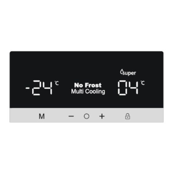
620 – ARES DISPLAY
Display and control panel
Using the Control Panel
1. Freezer temperature setting.
2. Super Freeze mode indicator
3. Fridge temperature setting
4. Super Cooling mode indicator
5. Holiday mode indicator
6. Eco mode indicator
7. Alarm indicator
8. Child Lock mode indicator
9. Screen selector
10. Decrease value
11. Increase value
12. Mode Selector
13. Child Lock Selector
1
OCTOBER 2021
Advertisement
Table of Contents

Summary of Contents for SOGEDIS 620
- Page 1 620 – ARES DISPLAY Display and control panel Using the Control Panel 1. Freezer temperature setting. 2. Super Freeze mode indicator 3. Fridge temperature setting 4. Super Cooling mode indicator 5. Holiday mode indicator 6. Eco mode indicator 7. Alarm indicator 8.
- Page 2 620 – ARES DISPLAY Display and control panel Super Freeze Mode Purpose • To freeze a large quantity of food that cannot fit on the fast freeze shelf. • To freeze prepared foods. • To freeze fresh food quickly to retain freshness.
- Page 3 620 – ARES DISPLAY Display and control panel Economy Mode Purpose Energy savings. During periods of less frequent use (door opening) or absence from home, such as a holiday, Eco program can provide optimum temperature whilst saving power. How to Use •...
- Page 4 620 – ARES DISPLAY Display and control panel During this mode: • Freezer and fridge temperature may be adjusted however the adjustment will not be made until Holiday Mode is cancelled. When Holiday mode is cancelled, the selected setting values will be activated and the temperature(s) will be adjusted.
- Page 5 620 – ARES DISPLAY Display and control panel Screen Saver Mode Purpose This mode saves energy by switching off all control panel lighting when the panel is left inactive. How to Use • Screen saver mode will be activated automatically after 30 seconds.
- Page 6 620 – ARES DISPLAY Display and control panel Freezer Temperature Settings • Press icon, until the ‘Freezer temperature setting’ is selected (#1). • Once Freezer temperature setting is selected, the temperature will flash. • Users can then use the up or down arrow ( ) to set the temperature (-16,- 17, -18,-19, -20,-21, -22, -23, -24 °C and Super Freeze Mode).
- Page 7 620 – ARES DISPLAY Flow of Air OCTOBER 2021...
-
Page 8: Refrigerant Cycle Diagram
620 – ARES DISPLAY Refrigerant Cycle Diagram PIPE FREEZER EVAPORATOR CONDANSER CONDANSER COOLER COMPRESSOR EVAPORATOR OCTOBER 2021... - Page 9 620 – ARES DISPLAY Used Component Resistance Values According To The Temperature Sensor (°C/Ohm Rates) ( For The Freezer Defrost and The Cooler Ambient Sensor) 45 °C/1kΩ -1 °C/6.2kΩ 35 °C/1.5kΩ -3 °C/6.8kΩ 30 °C/1.8kΩ -5 °C/7.5kΩ 25 °C/2.2kΩ -7 °C/8.2kΩ...
-
Page 10: Special Programs
620 – ARES DISPLAY Special Programs When the refrigerator works on first time; If the cooler compartment defrost sensor and the freezer compartment defrost sensor are hotter than -5°C, the test system works automatically. These below components are tested automatically every 5 seconds. - Page 11 620 – ARES DISPLAY Special Programs Cooler Defrosting Time The cooler defrost and the freezer defrost are operated parallel except those below. The cooler defrost will not work if the freezer defrost stops. The defrost process stops when the defrost sensor temperature feels 7ºC. At the low ambient temperature or when the compressor stops;...
-
Page 12: Abnormal Noise
620 – ARES DISPLAY Probable Faults Is the appliance too close to wall or It should be placed min 50cm heat sources (stove, central heating, distance from heat sources and oven, cooker etc.)? min 5 cm from electrical ovens. Unsufficient cooling Is the ambient temperature high? Raise the thermostat value. - Page 13 620 – ARES DISPLAY SERVICE MODE Push freezer temperature button continuously. During this time, open and close the cooler or freezer door for least 3 times. The appliance will enter service mode 3 sec. late. • If there is a faulty situation, error code will be observed on screen. Otherwise nothing will be on the screen.
- Page 14 620 – ARES DISPLAY User and Service Mode Error Message **Error codes can appear in normal use and they will be on a screen for 10 seconds. SR (Symbol blinks. No alarm sounds). USER MODE TEMPERATUR SERVICE MODE REACTION SENSOR...
- Page 15 620 – ARES DISPLAY User and Service Mode Error Message Low voltage error on display DEFECT TYPE DETAILS USER MODE REACTION SERVICE MODE REACTION Low voltage Power supply < 170 Display E 08 Display E 08 Cooling error on display Note: To prevent the wrong alarms, this alarm status is disabled on following conditions: •During the first 6 hours after the product was firstly connected.
- Page 16 620 – ARES DISPLAY Replacement of Upper Doors 1. Unscrew the screws fixing the left and right top hinge cover. Remove the hinge covers. 2. Disconnect the socket connections. 3. Unscrew the screws fixing the top hinges and remove it.
- Page 17 620 – ARES DISPLAY Replacement of Upper Doors 4. Remove the refrigerator doors by lifting them up. Note-1: To re –assembly the doors basically repeat the previous steps backwards. Note-2: After installing the upper doors , Note-3: Three out of Four screw...
- Page 18 620 – ARES DISPLAY Removing The Cooler Multi Flow Fan Motor 1- First remove the glass shelves and crispers. 2- Unscrew the crisper rails screws. 3. Remove refrigerator multi-flow caps and unscrew the screws after removing the multi flow OCTOBER 2021...
- Page 19 620 – ARES DISPLAY Removing The Cooler Multi Flow Fan Motor 4. Remove the fan motor by flexing the fan motor rubbers. 5. Place the rubbers (4 pcs) to the fan motor. 6. Place the fan motor. OCTOBER 2021...
- Page 20 620 – ARES DISPLAY Replacement of Freezer Multiflow 1- First remove the glass shelves and baskets. 2- Remove the fixing screws of middle rail and takeout the rail. 3- Takeout the freezer multiflow cover. Note: To re –assembly basically repeat the previous steps backwards.
-
Page 21: Removing The Thermal Fuse
620 – ARES DISPLAY Replacement of Freezer Fin Evap. Assy 1. Disconnect to evaporator connector. 2. Remove the evaporator by pulling forward (blue connector) Disconnect to evap.tray in a horizantal dicretion. heater. Fin Evap Fin Evap Tray Heater Heater Do not push it up or down. You may broke the fixing plastics. - Page 22 620 – ARES DISPLAY Replacement of Cooler Fin Evap. Assy 1. Disconnect to cooler evaporator and 2. Remove the evaporator by pulling forward sensor connector. in a horizantal dicretion. Cooler Fin Evap Connector Resim-1 Sensor Connector Do not push it up or down. You may broke the fixing plastics.
-
Page 23: Replacement Of Main Board
620 – ARES DISPLAY Replacement of Main Board Warning: Make sure the unit is unplugged 1. Remove the mainboard cover screws placed at the top of the unit and take the 2. Mainboard socket connections are described as below. 3.Remove the connection sockets carefully and remove the mainboard. - Page 24 620 – ARES DISPLAY Replacement of Main Board 5. Connect the sockets 4. Replace the main board. 6. Tidy up the cables, place the cover and fix the screws. OCTOBER 2021...
-
Page 25: Replacement Of Display
620 – ARES DISPLAY Replacement of Display CAUTION: The plug must be pulled out before the display is removed. 1. Display can be removed with the disassembly tool. Do not use any sharp objects to remove the display. 2. Disassembly tool code is 42152193 3. - Page 26 620 – ARES DISPLAY Replacement of Trizbar Trizbar is placed on the upper left door. 1. Open the left door and remove the fixing screws of the middle. 2. Disconnect to trizbar connections. OCTOBER 2021...
- Page 27 620 – ARES DISPLAY Replacement of Trizbar 3. Remove the trizbar group. OCTOBER 2021...
- Page 28 620 – ARES DISPLAY Replacement of Reed Switch There are two reed switch is under the upper door hinge covers. 1. Unscrew the screws fixing the left and right top hinge cover. Remove the hinge covers. 2. After removing the switch , take out the cable sockets for replacing.
Need help?
Do you have a question about the 620 and is the answer not in the manual?
Questions and answers