
Related Manuals for Brüel & Kjaer Vibro VIBRO Condition Monitoring 3

Summary of Contents for Brüel & Kjaer Vibro VIBRO Condition Monitoring 3
- Page 1 Hardware Installation instruction VIBRO Condition Monitoring 3 VCM-3 / VCM-3 Ex Keep it accessible for future reference...
- Page 2 Trademarks and Copyrights All trademarks, service marks, and/or registered trademarks used in this document belong to BK Vibro America Inc., except as noted below: Microsoft®, Microsoft® software, Windows®, Windows® operating system are either registered trademarks or trademarks of Microsoft Corporation in the United States and/or other countries. Trademarks used herein are the property of their respective owners.
-
Page 3: Table Of Contents
Brüel & Kjær Vibro │Installation instruction VCM-3 / VCM-3 Ex Table of Contents Table of Contents About this instruction ..................... 5 Scope ..............................5 Document conventions ........................5 Safe use of VCM-3 / VCM-3 Ex ................5 Disclaimer of liability ..........................5 Intended use ............................ - Page 4 Other connections ....................33 LAN interface, RJ45, SFP ........................33 Digital Output ............................34 RS485 interface ........................... 35 Internal storage and external storage devices ............ 36 External storage – SD card ........................ 36 External storage – USB memory stick ....................37 Maintenance ......................
-
Page 5: About This Instruction
Brüel & Kjær Vibro │Installation instruction VCM-3 / VCM-3 Ex About this instruction About this instruction Scope The scope of this document is to give instructions regarding the hardware installation of VCM-3 / VCM-3 Ex. This document also refers to the following instructions: •... -
Page 6: General Information
VCM-3 Ex variant is an EX-certified product and may be used in a hazardous area with flammable gases with apparatus groups IIC. The equipment is certified for use in ambient temperatures in the range of -30° C to +60° C and must not be used outside this range. -
Page 7: General Warnings
Brüel & Kjær Vibro │Installation instruction VCM-3 / VCM-3 Ex Safe use of VCM-3 / VCM-3 Ex General warnings 2.3.1 Staff requirements Transport, storage, installation, assembly, connection, commissioning, maintenance and service must be undertaken exclusively by qualified technicians. The following must strictly be observed: •... -
Page 8: Product Description
Product Description Main functionality The VCM-3 supports any state-of-the-art condition monitoring method and provides a platform for customizations and development of future new monitoring methods. VCM-3 provides early fault detection by using a large variety of descriptors (scalar values). Fast real time descriptors locked to the machine speed as well as advanced calculations using statistics and feature extraction from array measurements. -
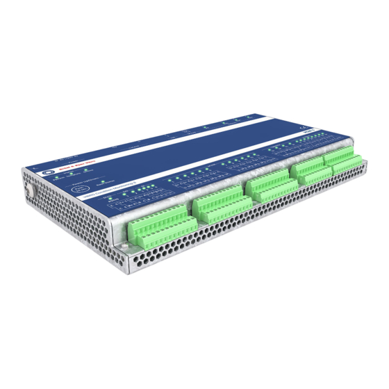
Page 9: Overview Of The Vcm-3 Unit
Brüel & Kjær Vibro │Installation instruction VCM-3 / VCM-3 Ex Product Description Overview of the VCM-3 unit Refer to VCM-3 Product specifications and ordering information document C107757.002 EN for further technical details. © Brüel & Kjær Vibro ● C107758.002 / V04 Page 9 of 42 Technical alterations reserved! UNRESTRICTED DOCUMENT... -
Page 10: The Vcm-3 Homepage
The VCM-3 Homepage The VCM-3 Homepage can be accessed from any web browser. The VCM-3 Homepage provides the following main functions: • On-site commissioning configuration and support • On-line check of descriptor measurements, time waveforms and spectrum (array) data. • VCM-3 system administration and commissioning such as upload of Standard Monitoring Templates, upload of firmware, password changes etc. -
Page 11: Technical Specification Summary
Brüel & Kjær Vibro │Installation instruction VCM-3 / VCM-3 Ex Product Description Technical specification summary This section only lists the most important technical data. Please refer to the Product specifications and ordering information document C107757002 for further details. Environmental In operation. -30 °C - 60 °C (-22F to +140F) in accordance to EN/IEC 60068-2-2. Ambient Temperature Applies to device and to device mounted in cabinet. -
Page 12: Mechanical Installation
Mechanical installation • “The equipment shall only be used in an area of at least pollution degree 2, as defined in IEC 60664-1.” • “The equipment shall be installed in an enclosure that provides a minimum ingress protection of IP 54 in accordance with IEC 60079-0”. •... - Page 13 Brüel & Kjær Vibro │Installation instruction VCM-3 / VCM-3 Ex Mechanical installation Adaptor Plate Mounting The VCM-3 can also be mounted in a cabinet using an adaptor plate. The screw holes fit the holes used for the DIN clamps. © Brüel & Kjær Vibro ● C107758.002 / V04 Page 13 of 42 Technical alterations reserved! UNRESTRICTED DOCUMENT...
-
Page 14: Basic Operation Of The Vcm-3
Basic operation of the VCM-3 First time the VCM-3 is powered up The very first time a VCM-3 is powered up it will run with a factory default template. The intention of the factory template is to enable a first test of the installation. The factory default template provides the necessary descriptors for completing the initial commissioning procedure of the VCM-3. -
Page 15: Power Up/Down
Brüel & Kjær Vibro │Installation instruction VCM-3 / VCM-3 Ex Basic operation of the VCM-3 Power Up/Down When the 24 V power supply is connected, the VCM-3 will automatically boot up, the boot process is complete when the Boot Status LED shows constant green light. If the VCM-3 shall be powered down or powered up, the normal procedure listed below is to use the Power Up/Down button named Push 10 sec. - Page 16 Power Down procedure Action Boot Status LED Explanation Power Down Soft Power down will close down the VCM-3 in an orderly (Normal) manner where it is ensured that all data is stored in non- Press the power volatile memory before power is taken off. switch for 3 seconds.
-
Page 17: Reset To Default Ip Address
Brüel & Kjær Vibro │Installation instruction VCM-3 / VCM-3 Ex Basic operation of the VCM-3 Reset to default IP address In the case that the IP address is unknown it is possible to access the VCM-3 using the factory default IP address. -
Page 18: Power Connections
Power connections Power connection – Supply current Minimum temperature rating of the cable to be connected to the field wiring terminals, power supply shall be 85 °C, minimum temperature rating for wiring to sensors and others 80 °C. The VCM-3 (non Ex) is powered by 24 V DC. W We recommend the use of a switch mode power supply (e.g., PULSE Types ML50.1... -
Page 19: Power Connection - External Sensor Power
Brüel & Kjær Vibro │Installation instruction VCM-3 / VCM-3 Ex Power connections IMPORTANT NOTE! A surge protected +24 V (nominal) SELV DC power supply must be used as supply for the VCM-3 / VCM-3 Ex. (SELV – Safety Extra Low Voltage). The power supply must have an output voltage from +18 V to +26 V and a current capacity of minimum 1,6 A and max. -
Page 20: Termination Of Sensor Signals
Termination of sensor signals The following section describes how to connect the various sensors and inputs to the VCM-3. The various types of channel inputs must have been enabled in the VCM-3 monitoring template in order to be used. If channel groups are not supported, please do not connect. A specific or custom “Standard (Master) Monitoring Template”... -
Page 21: Shielding
Brüel & Kjær Vibro │Installation instruction VCM-3 / VCM-3 Ex Termination of sensor signals Shielding It is very important that the shields of the sensor cables and the housing of VCM-3 are connected to the same ground potential. That is, to the cabinet where they are mounted. On the side of VCM-3 housing a ground cable can be fastened to the cabinet. -
Page 22: Constant Current Line Drive Accelerometers (Ccs) Channel 1-12
Constant current line drive accelerometers (CCS) channel 1-12 Constant current line drive accelerometers (CCS) This type of sensors needs a constant current, which is supplied by the VCM-3 unit. Examples of high quality accelerometers offered by Brüel & Kjær Vibro includes: •... -
Page 23: Brüel & Kjær Vibro As-247 Dual Axis Accelerometers On Channel 11-12
Brüel & Kjær Vibro │Installation instruction VCM-3 / VCM-3 Ex Termination of sensor signals Brüel & Kjær Vibro AS-247 dual axis accelerometers on channel 11-12 AS-247 sensor mounting. AS 247 is a bi-axial sensor, that is, it produces two output signals one for each axis. -
Page 24: Brüel & Kjær Vibro As-247 Dual Axis Accelerometers On Channel 1-10
Brüel & Kjær Vibro AS-247 dual axis accelerometers on channel 1-10 AS-247 sensor mounting. AS 247 is a bi-axial sensor, that is, it produces two output signals one for each axis. In the figure these two axes are denoted XSIG and ZSIG. -
Page 25: Displacement Sensors (Proximity Probes) Channel 1-10
Brüel & Kjær Vibro │Installation instruction VCM-3 / VCM-3 Ex Termination of sensor signals Displacement sensors (proximity probes) channel 1-10 Displacement sensor mounting on channel 1-10 NOTE! This prescription is only valid for channel 1-10. On channel 11 and 12 no SP terminal is available. -
Page 26: Displacement Sensors (Proximity Probes) Channel 11 And 12
Displacement sensors (proximity probes) channel 11 and 12 Displacement sensor mounting on channel 11 and 12 If a displacement sensor shall be mounted on channel 11 or 12 the -24 V sensor power cannot be taken directly from the channel connections as the sensor power for channel 11 and 12 is assigned only to a +24 V. In this case the sensor power can be taken from an unused sensor power terminal (SP) on the VCM-3. -
Page 27: Displacement Sensors (Proximity Probes) Channel 13-16
Brüel & Kjær Vibro │Installation instruction VCM-3 / VCM-3 Ex Termination of sensor signals Displacement sensors (proximity probes) channel 13-16 Displacement sensor mounting If high absolute accuracy is required on the displacement measurements, e.g. for position measurements channel 13- 16 can be applied for proximity probes. This type of sensor needs -24 VDC sensor power. -
Page 28: Ma Input Channel 17-24
7.10 4-20 mA input channel 17-24 4-20 mA input mounting. Current for the loop supplied by the VCM-3 This input is used for 4-20 mA signals provided, for example, by a temperature transmitter. The current loop is driven by the VCM-3 power supply. The current loop input provides “NAMUR”... -
Page 29: Speed Sensor, Proximity Switch, Pnp And Npn Type
Brüel & Kjær Vibro │Installation instruction VCM-3 / VCM-3 Ex Termination of sensor signals 7.11 Speed sensor, proximity switch, PNP and NPN type About PNP and NPN sensor types This type of sensor is for measuring the speed of a shaft. General information The +24 VDC supply for this type of sensor is supplied by the VCM-3 unit. - Page 30 Speed Sensor, NPN type – mounting The +24 VDC supply for this type of sensor is supplied by the VCM-3 unit. NOTE! The color coding of the wires follows the standard for proximity switches. NOTE! A resistor between 1 kΩ and 10 kΩ needs to be mounted.
-
Page 31: Rogowski Probe For Current And Power Measurements
Brüel & Kjær Vibro │Installation instruction VCM-3 / VCM-3 Ex Termination of sensor signals 7.12 Rogowski probe for current and power measurements About Rogowski probes (Rogowski coils) An alternating or pulsed current in a conductor develops a magnetic field and General information the interaction of this magnetic field and the Rogowski coil local to the field gives rise to an induced voltage within the coil. -
Page 32: Digital Inputs
7.13 Digital inputs Digital Inputs The Digital Input can be used to trigger the capture of time waveforms but can also be used for other purposes such as trip override functions for the alarm system. The Digital Input can receive a signal from the digital output on another VCM-3, thus making it possible to synchronize time waveform capture on several VCM-3 units with a delay less than 100ms. -
Page 33: Other Connections
Brüel & Kjær Vibro │Installation instruction VCM-3 / VCM-3 Ex Other connections Other connections Please note that cables for these connections shall have a minimum temperature rating of 80 °C LAN interface, RJ45, SFP LAN interface connections The VCM-3 has four network connections: Three for RJ-45 connectors and one for optical fiber. The connectors are organized as shown below. -
Page 34: Digital Output
Digital Output NOTE! The Digital Output functionality is supported from VCM-3 Firmware version 1.15 or higher. Digital Output – connections The digital output on VCM-3 is implemented using photo relays. The photo relays used for the digital outputs are rated for an on-current of 1A up to 50 degC and 0,5 A at 85 C. The max. -
Page 35: Rs485 Interface
Brüel & Kjær Vibro │Installation instruction VCM-3 / VCM-3 Ex Other connections RS485 interface RS 485 connections This connection is often utilized for serial MODBUS interface (not to be confused with Modbus TCP/IP). The interface in the VCM-3 supports both full duplex and half duplex communication. Please refer to the connection diagram below for details. -
Page 36: Internal Storage And External Storage Devices
Internal storage and external storage devices Any external storage device to be used with the VCM-3 must be formatted with a compatible file system format. Currently supported formats for the USB and SD ports are: FAT32, exFAT and ext4 filesystems. A maximum size of 1TB storage devices is currently supported by VCM-3. -
Page 37: External Storage - Usb Memory Stick
Internal storage and external storage Brüel & Kjær Vibro │Installation instruction VCM-3 / VCM-3 Ex devices External storage – USB memory stick USB information The VCM-3 bus interface supports USB storage devices which comply to the USB 2.0 standard. USB 3.0 only storage devices or devices with a current consumption >500 mA are currently not supported. -
Page 38: Maintenance
Maintenance NOTE! Maintenance and service work must only be performed by trained qualified personnel! VCM-3 does not require any regular service or maintenance. It contains no moving parts. Input calibration has been done at the factory and no further calibration is needed. For recalibration please contact Brüel &... -
Page 39: Appendix 1: Floating Vcm-3 Chassis/Ground Connection
Appendix 1: Floating VCM-3 Brüel & Kjær Vibro │Installation instruction VCM-3 / VCM-3 Ex chassis/ground connection Appendix 1: Floating VCM-3 chassis/ground connection Special set-ups may require that the VCM-3 is isolated from the surrounding ground potential (floating - as for instance in some maritime cases). Since ground (chassis) and signal return (GND) are connected internally in the VCM-3, the required isolation in these cases must be implemented outside the VCM-3. -
Page 40: Appendix 2: Ce Conformity Declaration
Appendix 2: CE conformity declaration © Brüel & Kjær Vibro ● C107758.002 / V04 Page 40 of 42 Technical alterations reserved! UNRESTRICTED DOCUMENT... - Page 41 Brüel & Kjær Vibro │Installation instruction VCM-3 / VCM-3 Ex Appendix 2: CE conformity declaration © Brüel & Kjær Vibro ● C107758.002 / V04 Page 41 of 42 Technical alterations reserved! UNRESTRICTED DOCUMENT...
- Page 42 Contact Brüel & Kjær Vibro GmbH Brüel & Kjær Vibro A/S BK Vibro America Inc Leydheckerstrasse 10 Lyngby Hovedgade 94, 5 sal 1100 Mark Circle 64293 Darmstadt 2800 Lyngby Gardnerville NV 89410 Germany Denmark Phone: +49 6151 428 0 Phone: +45 69 89 03 00 Phone: +1 (775) 552 3110...
Need help?
Do you have a question about the VIBRO Condition Monitoring 3 and is the answer not in the manual?
Questions and answers