Table of Contents
Advertisement
INSTRUCTION
INSTRUCTION
INSTRUCTION
INSTRUCTION
ENGINE
ENGINE
ENGINE
ENGINE
DIS-
DIS-390
DIS-
DIS-
Before using, be sure to read this manual for the sake of safety.
Be sure to observe the items under symbol marks
CAUTION
and
"
Always keep this manual at your machine for the sake of safety.
2-8-5, Nihonbashi-horidomecho, Chuo-ku, Tokyo, 103-8566, Japan
DENYO
DENYO
DENYO
DENYO
COMPRESSOR
COMPRESSOR
COMPRESSOR
COMPRESSOR
390
390
390ES
390ES-C
390
390
390
390ES-D
390
390
390
for the sake of safety.
"
No. E48402 00204C
MANUAL
MANUAL
MANUAL
MANUAL
ES
ES
ES
ES-C
ES-C
ES-C
ES-D
ES-D
ES-D
WARNING
"
"
Advertisement
Table of Contents

Subscribe to Our Youtube Channel
Related Manuals for Denyo DIS-390ES

Summary of Contents for Denyo DIS-390ES
- Page 1 No. E48402 00204C INSTRUCTION INSTRUCTION MANUAL MANUAL INSTRUCTION INSTRUCTION MANUAL MANUAL DENYO DENYO DENYO DENYO ENGINE ENGINE COMPRESSOR COMPRESSOR ENGINE ENGINE COMPRESSOR COMPRESSOR DIS- DIS-390 DIS- DIS- 390 390 390ES ES ES ES 390 390ES-C ES-C 390 390 ES-C ES-C 390...
- Page 2 FOREWORD * Your machine is a portable type engine compressor. (Specifications: See p.54) * Do not install, operate or repair this machine without reading this operating manual. * This engine compressor (machine) must be operated by a person having sufficient knowledge and skill for the sake of safety.
-
Page 3: Table Of Contents
- Contents - 1.Safety Precautions ------------------------------------------------------------------------------------- 2.Construction --------------------------------------------------------------------------------------------- 2-1 Outline and part names ---------------------------------------------------------------------- 2-2 Instrumental panel and part names ------------------------------------------------------ 2-3 Meters ---------------------------------------------------------------------------------------------- 2-4 Use of switches and controllers ------------------------------------------------------------- 3.Operation ------------------------------------------------------------------------------------------------- 3-1 Checking prior to operation ------------------------------------------------------------------ 3-2 Starting -------------------------------------------------------------------------------------------- 3-3 Starting under cold weather ----------------------------------------------------------------- 3-4 Precautions during operation --------------------------------------------------------------- 3-5 Stopping -------------------------------------------------------------------------------------------... -
Page 4: Safety Precautions
1.Safety Precautions In order to ensure safe operation, the following symbols are used for explanation of the machine operation. The following symbols, found throughout this manual, alert you to potentially dangerous conditions to the operator, service personnel, or the equipment. WARNING: This symbol refers to a hazard or unsafe practice which can result in severe personal injury or death. - Page 5 Safety label Safety labels are attached to the following positions of the machine. * Keep these safety labels clean at all times. * When safety labels are spoiled or lost, contact distributor or our office specifying the nameplate No. shown below and ask for new ones. 1.Warning : Moving parts (B9050 0050) 2.Caution : Hot surfaces...
- Page 6 WARNING ENGINE EXHAUST can kill. ■ Insufficient ventilation may lead to death due to lack of oxygen or poisoning by exhaust gases. * Do not use the machine in a place of poor ventilation or in a place where exhaust gases stays. * Do not use the machine indoors or in storehouse, tunnel, ship hold, tank, etc.
- Page 7 WARNING DIESEL FUEL can cause fire or explosion. ■ Fuel and oil are flammable. Incorrect handling results in danger of ignition or fire. * When fuel needs to be supplied to the machine, be sure to stop the engine. Refrain from smoking. Keep the machine away from fire.
- Page 8 CAUTION HOT PARTS can burn skin. ■ High temperature units are located in the machine. (Note that these units are very dangerous if they are used incorrectly.) * Be sure to close the door and lock it during operation. * If the door needs to be opened during operation, do not get your hands and head in the machine to prevent unexpected burns.
- Page 9 CAUTION High pressure Dangerous High Pressure. Never open the oil filler ■ port, while high pressure remains inside. Otherwise, A serious injury can result. Be sure to stop engine and release the inside pressure before filling oil. CAUTION High pressure remains Dangerous Residual Pressure.
- Page 10 CAUTION Transportation ■ Do not lift the machine at the support hook or the ladder because it is not strong enough for lifting and may cause a falling accident. * When lifting the machine, use the hanger located at the roof center.
- Page 11 CAUTION Run away ■ Be sure to set the wheel stoppers expect for moving. Otherwise, the unit may move or run away and can cause a serious accident. CAUTION Safety instructions on Trailer Improper operating of the trailer can result in the accident to severe injury or death. For moving or parking, be sure to keep the following instructions: 1.
-
Page 12: Construction
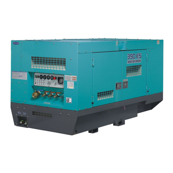
2.Construction 2-1 Outline and part names 1. Instrumental panel 9. Compressor lube oil drain port 2. Air outlet valves 10. Engine lube oil drain port 3. Fuel inlet port 11. Coolant drain port 4. Lifting hook 12. After-cooler drain (ES-C/ES-D) 5. -
Page 13: Instrumental Panel And Part Names
2-2 Instrumental panel and part names The instruments panel contains all the meters, instruments and switches necessary for operating the machine: 1. Preheat lamp 11. Engine lube oil pressure warning lamp 12. Water temperature warning lamp 2. Starter switch 13. Charging warning lamp 3. -
Page 14: Meters
2-3 Meters Engine indicators (1) Tachometer This meter indicates the number of revolutions of the engine. (2) Hour meter This meter indicates the total running time of the engine. This meter is built in the tachometer. (3) Water temperature gauge This is normal when it indicates 82 to 95℃... - Page 15 Compressor indicators (1) Delivery air pressure gauge This meter indicates pressure of delivered air by compressor. (2) Discharge air temperature gauge This meter indicates temperature of discharge air. This is normal when it indicates 60 to 105℃ during operation. [Note] If it indicates higher values, close air outlet valves.
- Page 16 Indicator / warning lamps (1) Oil separator indicator When the Oil Separator Element is blinded, this indicator draws near the red range. While working, the green range shows its normality, the red range shows it should be replaced. (2) Engine air filter When the engine air filter element is blinded, this lamp lit on.
- Page 17 (6) Engine low speed This lamp lit on, if engine revolution failed abnormally. If this lamp lit on during operation, the emergency stop device immediately operates to shut down the engine automatically. ENG.LOW SPEED (7) Engine Oil If the machine is in normally operation, this lamp lit off. When the starter switch is turned to "RUN"...
-
Page 18: Use Of Switches And Controllers
2-4 Use of switches and controllers (1) Starter switch Functions: ① STOP This switch should be set in this position unless the machine is in operation. The key can be inserted or pulled out in this position. ② RUN This switch should be set in this position when the machine is in operation. - Page 19 (3) Emergency stop button Functions: This is a pushbutton to stop the engine urgently on emergency case. Do not push the button without emergency case.
-
Page 20: Operation
3.Operation - From pre-start check to shut down - Be sure to check the machine prior to starting. 1.. Checking prior to operation 2.. Starting 3.. Starting under cold weather 4.. Precautions during operation 5.. Stopping 6.. Emergency stop and monitor display 3-1 Checking prior to operation WARNING MOVING PARTS can cause severe injury. - Page 21 Inspection: (1) Check on engine lube oil (Read the instruction manual for the engine furnished separately.) ① Checking the level of engine lube oil by the dipstick. Make sure the oil level is always between H and L. ② When it is below the low limit, supply oil immediately.
- Page 22 (4) Check on radiator coolant (Read the instruction manual for the engine furnished separately.) WARNING HOT COOLANT can cause severe scalds. ■ If the radiator cap is opened while the water temperature is high, steam or hot water will spout out. * During operation or immediately after stopping the machine, do not open the radiator cap while the water temperature is high.
- Page 23 (5) Check on fan belt (Read the instruction manual for the engine furnished separately.) ① Check the belt for tension and elongation. Also, check it for damage. Replace if necessary. ② For adjustment or replacement of the belt, refer to the instruction manual for the engine. Parts number of fun belt Y06020 11435 (ISUZU 897232-2520) Press {about 100N(10kgf)}) the position shown by arrow...
- Page 24 (7) Check on battery fluid CAUTION The battery fluid is dilute sulfuric acid. Improper handling will cause unexpected burns. * When the batter fluidy gets on your clothes or skin, wash it out with a large volume of water immediately. If it gets in your eyes, wash with a large volume of water immediately and consult your doctor.
-
Page 25: Starting
3-2 Starting (1) Fully close air outlet valves and start-run valve. (2) Turn the unloader valve to the "START" position. [Caution] Starting the engine with the unloader valve set to the "RUN" position will shorten the life of the machine and may cause hazards to an operator and neighboring persons. Be sure to start it after confirming start the unloader valve is set to the "START"... -
Page 26: Starting Under Cold Weather
"RUN" position. 3-4 Precautions during operation Occasionally check all gauges and meters on the instrument panel to ensure that the compressor is operating under the standard conditions stated below: DIS-390ES/ES-C/ES-D Delivery air pressure gauge(MPa) 0.70 (full load) 0.74~0.80 (no load) -
Page 27: Stopping
3-5 Stopping (1) Close air outlet valve(s). The speed regulator will reduce engine speed to the idle. Put the machine in cooling operation for about 5 minutes. (2) Turn the starter key to the "STOP" position. The engine stops and the compressed air remaining in the compressor will be automatically discharged. - Page 28 1. OIL PRESS. If the display lamp is not lit, engine lube oil pressure is normal(150kPa or more). Should it come on during operation, the emergency stop device will immediately stop the engine. This lamp is kept lit on until the starter switch is turned off. 2.
-
Page 29: Protection Device
4.Protection device Protection devices and emergency stop devices are provided for protection of the machine against trouble during operation. When the running caution lamp lights, stop the engine immediately. Check and remove the cause of trouble. Table of protection device Indicate by warning lamp action stop the engine... -
Page 30: Lubrication Oil, Cooling Water And Fuel Etc
Use oil according to ambient temperature referring to the table below. Ambient temperature (℃) ←----SAE20----→ ←----SAE30----→ ←------SAE5W-20------→ ←--------SAE10W-30-------→ ←-------SAE15W-40---------- [Note]: Do not mix with different kind of oil, or else, it deteriorates the oil quality. (3) Quantity of replacement oil DIS-390ES/ES-C/ES-D Value in parentheses is filter capacity. -
Page 31: Cooling Water
40%: -20℃ 50%: -30℃ Replenish LLC of the same brand and concentration with the one currently used. In general, LLC needs to be replaced every 2 years. (2) Total quantity of cooling water DIS-390ES/ES-C/ES-D Value in parentheses is reserve tank capacity. -
Page 32: Fuel
5-4 Safety valve The pressure safety valve is factory adjusted and sealed prior to shipment of the compressor.Do not remove the seal or try to adjust the valve. Adjustment value of safety valve DIS-390ES/ES-C/ES-D 0.88MPa... -
Page 33: Regulator
5-5 Regulator The compressor has been correctly adjusted prior to shipment from the factory, and rarely requires further adjustment, if ever. Should it require any adjustment, however, as a result of overhauling or other cause, follow the following procedures: (1) Prior to starting the engine, check whether or not the engine governor lever is set to the high-speed stopper. -
Page 34: Compressor Lube Oil
Use lube oil exclusively for this series of rotary compressors. (1) Recommended compressor lube oil and its standard replacement interval Compressor lube oil : Denyo genuine compressor oil Corena Oil RS32 (XHVI) Shell Replacement interval : Every 1000 hours for normal operation (2) Precautions on oil replacement Never mix lube oils of different brands or fresh lube oil with in the tank. - Page 35 (4) Lube oil changing procedures 1) Operate the compressor for a while to warm the oil so that it may be drained easily. 2) Shut down the compressor and confirm that the air pressure has reached zero. Then, open the drain valve. Disconnect the oil cooler drain plugs and drain the oil remaining in each pipe and in the oil cooler.
-
Page 36: Handling Of Battery
6.Handling of battery CAUTION BATTERY ■ Battery generates flammable gases. Improper handling may lead to explosion or serious injury. * Battery should be charged in a well ventilated location. Otherwise, flammable gases are accumulated which may be ignited and exploded. * When connecting a booster cable, do not jumper the terminals (+ and -). -
Page 37: Caution On Battery Charge
6-1 Caution on battery charge Charging of loaded battery * Disconnect the wiring cable from the battery terminals before charging. (Otherwise, the alternator may be damaged due to unusual voltage applied to the alternator) * When disconnecting the wiring cables from the battery terminals, remove the ground cable first. -
Page 38: Connection Of Booster Cable, And Installation
6-2 Connection of booster cable, and installation When the engine is started using booster cables, connect the cables as follows. (1) Connection of booster cable ① Connect the clip of the booster cable "A" to the terminal "+" of the machine in trouble. ②... -
Page 39: Periodical Checking And Maintenance
7.Periodical checking and maintenance 7-1 Maintenance schedule 50 hours: Checking/first 50 hours * Replacement of engine oil * Replacement of engine oil filter cartridge 100 hours: Checking/every 100 hours * Lubricating speed regulator * Cleaning of air cleaner element * Cleaning of after-cooler filter (ES-C,ES-D) 250 hours: Checking/every 250 hours * Checking on battery specific gravity * Replacement of engine oil... -
Page 40: Checking/First
7-2 Checking/first 50 hours (1) Replacement of engine oil Replace the engine oil first 50 hours. ① Remove the engine oil drain plug or open the engine oil drain valve, and discharge oil completely. It can be discharged easily when the engine is warm. ②... -
Page 41: Checking/Every 100 Hours
7-3 Checking/every 100 hours (1) Lubricating speed regulator (2) Cleaning of air cleaner element This element should be cleaned, regardless of operating time, when the air filter warning lamp lit on. - Dry dust clings on element - Remove the air cleaner element and clean the element with dry and clean compressed air. -
Page 42: Checking/Every 250 Hours
7-4 Checking/every 250 hours (1) Checking on battery specific gravity. If battery is likely to be discharged due to failure in startup of the engine, measure the specific gravity of battery acid. The relation between battery charge condition (charging rate) and specific gravity is as shown below. -
Page 43: Checking/Every 500 Hours
7-5 Checking/every 500 hours (1) Replacement of engine oil filter cartridge Replacement is refer to 「7-2.(2) Replacement of engine oil filter cartridge See p.37 」. (2) Checking operation of the safety valve Confirm daily that the safety valve operates correctly. If the safety valve releases air by pulling the lever in a no-load condition, it is normal. - Page 44 (4) Replacement of fuel filter cartridge ① Remove the cartridge type element (cartridge) using filter wrench. ② Clean the filter base. Coat the packing of new cartridge with engine oil thin. Then, mount the cartridge. ・When mounting, tighten the cartridge from 3/4 turn by using filter wrench after the packing is fitted to the seal of the filter base.
-
Page 45: Checking/Every 1000 Hours
7-6 Checking/every 1000 hours (1) Replacement compressor oil Replacement is refer to「5-6.(4) Lube oil changing procedures (See p.32).」 (2) Replacement compressor oil filter ① Remove the cartridge type element (cartridge) using filter wrench. ② Clean the filter base. Coat the packing of new cartridge with engine oil thin. - Page 46 (4) Checking on diaphragm in capacity regulator Check the diaphragm in capacity regulator, and replace it with a new one as required. Parts number of diaphragm Y06030 44208 (5) Replacement of diaphragm in pressure regulator valve Parts number of diaphragm Y06034 00020 (6) Replacement of O-ring in minimum pressure valve Remove the minimum pressure valve cover ,...
- Page 47 (9) Cleaning of radiator and oil cooler When the fin or tube is blinded, it should be cleaned with steam or high pressure water. [Note] When a high pressure washer is used, spray water from a place about 1.5m away to prevent damage to the fin or tube. (10) Cleaning of after-cooler (ES-C, ES-D) and after-warmer (ES-D) When the fin or tube is blinded, it should be cleaned with steam or high pressure water.
-
Page 48: Checking/Every 2000 Hours
7-7 Checking/every 2000 hours (1) Checking of oil separator element When the oil in the discharge air seems to have increased, check and replace oil separator element . As with an air cleaner element, the service life of an oil separator element differs substantially depending upon operating conditions. -
Page 49: Table Of Periodical Maintenance And Checking
7-8 Table of periodical maintenance and checking ◇;Check or Clean ○;Replacement daily every every every every every 100h 250h 500h 1000h 2000h Engin e ◇ Check on engine lube oil ◇ Check on compressor lube oil ◇ Drain condensed water from oil chamber drain ◇... -
Page 50: Trouble Shooting And Countermeasures
8.Trouble shooting and Countermeasures Should the machine be out of order during operation, check for causes and take appropriate measures: 8-1.ENGINE DOES NOT START Starter does not rotate or rotates only slowly. Battery has been discharged …Check electrolyte level and specific gravity. Battery terminals are disconnected, loosened, and/or degraded …Clean and securely connect. - Page 51 8-2 ENGINE STOPS DURING OPERATION (1) IF THERE IS SOMETHING WRONG WITH THE COMPRESSOR: Pressure setting is too high. Pressure regulator is not correctly adjusted …Lower pressure setting of the regulator. pressure regulator is defective …Call service shop. Air leaks from pressure regulator pipes …Check and repair leaking portions.
- Page 52 (3) IF THERE IS SOMETHING WRONG WITH ELECTRIC INSTRUMENTATION: Emergency stop circuit is abnormal Switch or sensor is defective …Check and repair Wiring to water temperature switch, hydraulic pressure switch, discharge air temperature sensor is disconnected …Call service shop. Engine control unit is defective …Check and repair Call service shop.
- Page 53 8-6 ENGINE SPEEDS DOWN BEFORE AIR PRESSURE REACHES OPERATING PRESSURE. Unloader valve is not set to “RUN” position …Reset. pressure regulator valve is not correctly adjusted …Readjust. Fuel filter is clogged …Clean filter element. Fuel is deteriorated or different …Use light oil. Engine air cleaner is clogged …Clean air cleaner element.
- Page 54 8-9 OIL IS MIXED IN DELIVERED AIR (oil not fully separated) The machine is not installed on level …Install it on level ground (allowable inclination is ground 5°forward/backward and left/right directions). Delivered air pressure is low Set pressure retaining valve to 0.42 to 0.7 MPa. Compressor oil level is higher than the …Confirm than the level is within the specified upper limit...
- Page 55 8-11 COMPRESSOR AIR TEMPERATURE IS HIGH Delivery pressure is high …Readjust the set pressure. Re-confirm surrounding conditions …Reduce suction of exhaust gas. Compressor oil filter is clogged …Check and clean. Fan belt is loosened …Check and retighten. Oil cooler cores are clogged …Clean.
-
Page 56: Long-Term Storage
9. Long-term storage When the machine is to be stored for a long period of time, choose a cool place free from moisture and dust, and observe the following points. (1) Remove dirt clung the machine and clean it thoroughly. If painting is peeled off, it should be repaired. -
Page 57: Service Data
10.Service data 10-1 Specifications DIS-390ES DIS-390ES-C DIS-390ES-D MODEL Trailer Trailer Trailer type type type type type type Compressor Type Single stage, oil-cooled, screw type rotary compressor Actual free air delivery 11.0 (390) /min(cfm) Operating pressure MPa(psi) 0.7 (102) Lube oil capacity L(gal) 50 (13.2) -
Page 58: Outline Drawing
10-2 Outline drawing ・ ・ ・ ・ DIS-390ES... - Page 59 ・ ・ ・ ・ DIS-390ES(trailer type)
- Page 60 ・ ・ ・ ・ DIS-390ES-C...
- Page 61 ・ ・ ・ ・ DIS-390ES-C(trailer type)
- Page 62 ・ ・ ・ ・ DIS-390ES-D...
- Page 63 ・ ・ ・ ・ DIS-390ES-D(trailer type)
-
Page 64: Combined Piping Diagram
10-3 Combined Piping Diagram ・ ・ ・ ・ DIS-390ES... - Page 65 ・ ・ ・ ・ DIS-390ES-C...
- Page 66 ・ ・ ・ ・ DIS-390ES-D...
-
Page 67: Engine Wiring Diagram
10-4 Engine wiring diagram...
Need help?
Do you have a question about the DIS-390ES and is the answer not in the manual?
Questions and answers