Table of Contents
Advertisement
Quick Links
1.0
INTRODUCTION
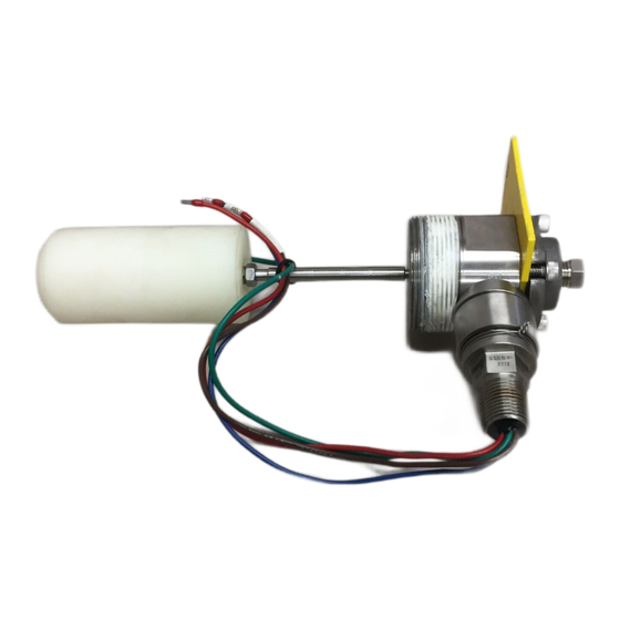
The Ruelco Model 30C2 (2" NPT
Mount)/31C2 (Flange Mount) 3-way
pneumatic liquid level switch is
typically mounted directly into a tank or
vessel or in an optional external cage
(See Figures 1,2). Horizontal or hang
down displacer elements are available.
This displacer operates a pneumatic
valve when a liquid in a tank or a
pressurized vessel reaches a
predetermined level. The operation
mode, as a high or a low level sensor, is
selected by rotating the valve body 180
degrees.
TYPICAL MOUNTING OF MODEL 30C2
LEVEL SWITCHES
FIG. 2
MODEL 30C2 SHOWN IN
MODEL 3C01 EXTERNAL CAGE
FIG. 1
FLEX LEVEL
LIQUID LEVEL SWITCH
OPERATION MANUAL
OMP# LS-3 – 5/19
2.0
OPERATION (See Fig. 3)
When in the non-tripped condition, the
3-way pneumatic valve is configured as
a normally open valve when set for high
level detection and as a normally closed
valve when set for low level detection.
When used as a high level sensor, the
valve will allow air flow from inlet to
outlet when the liquid is below the
displacer. When liquid contacts the
displacer, the valve will block the inlet
pressure and vent the outlet pressure.
When used as a low level sensor, the
valve will allow air flow from inlet to
outlet when the liquid is above the
displacer. When liquid no longer
contacts the displacer, the valve will
block the inlet pressure and vent the
outlet pressure.
Because of the balanced design of the
valve, variations in instrument pressure
from 5 to 50 PSI will have little effect
on level switch performance.
The switch senses a change in the
buoyancy of a displacer assembly inside
a pressurized or unpressurized vessel.
To transmit the buoyancy change, a
pivoting action is used. The I.D. of the
cone contacts the pivot attached to the
push rod and valve body. The o-ring
(provides a pressure tight seal between
the body and the shaft of the cone
protruding through the o-ring. Pressure
in the vessel, if any, acting on the shaft
of the cone, forces the cone against the
pivot point on the valve body. The
position of this point, at the center of the
o-ring, allows the displacer assembly to
move up or down.
3-WAY
Advertisement
Table of Contents

Summary of Contents for Ruelco 30C2
- Page 1 LIQUID LEVEL SWITCH OPERATION MANUAL OMP# LS-3 – 5/19 INTRODUCTION OPERATION (See Fig. 3) The Ruelco Model 30C2 (2” NPT Mount)/31C2 (Flange Mount) 3-way When in the non-tripped condition, the pneumatic liquid level switch is 3-way pneumatic valve is configured as...
- Page 2 If a cage with butt weld connections is HIGH LEVEL OPERATION used, the level switch should be (NORMALLY OPEN) removed from the cage before welding. This will prevent weld sparks from As the liquid level rises and begins to damaging the displacer assembly. cover the displacer assembly, the Remove the switch from the cage as per buoyancy in the liquid reduces the...
- Page 3 longer than the 2” connection on which it is being installed. (See Figure 4). 3.2.3 Apply an anti-galling compound to the 2” NPT female thread into which the switch is installed TOOLS REQUIRED: A 2.125” open end wrench or a suitable adjustable Screw the level switch...
-
Page 4: Changing Mode Of Operation
UNPRESSURIZED CAGE CAUTION: If using a pipe wrench, do OR VESSEL not allow the wrench jaws to contact the spring cap. Wrench forces may damage 4.1.1 Verify that no pressure is the cap and prevent the switch from present in the cage or vessel. If operating properly. - Page 5 the end of the cone that is protruding through the body PARTIAL DISASSEMBLY will move the valve body (3-WAY POPPET VALVE REPAIR) outward as the two screws are CAUTION: ONLY THE VALVE BODY turned. When the valve body CAN BE REMOVED FROM THE LEVEL has stopped moving, remove the four screws completely.
-
Page 6: Tools Required
PRESSURE WILL HAVE TO BE 5.2.7 Using pliers to grip the O.D. of the REMOVED FROM THE CAGE OR pivot, rotate it counterclockwise to VESSEL BEFORE ANY FURTHER unthread it from the valve body. DISASSEMBLY IS POSSIBLE. 5.2.8 Push the threaded end of the cone 5.1.5 Loosen the retainer and the stinger can through the body. -
Page 7: Recommended Maintenance
Install the valve stem o-ring and the 7.0 RECOMMENDED MAINTENANCE valve retainer o-ring. Lubricate the valve stem o-ring and insert the valve PROCEDURE INTERVAL stem into the valve retainer. Test switch in place with every 30 days Using the needle nose pliers, install the Process liquids to check valve retainer with valve stem installed For proper operation. -
Page 8: Troubleshooting
TROUBLESHOOTING PROBLEM PROBABLE CAUSE RECOMMENDED ACTION 1) Level switch does not A) Debris blocking the vent port Clean vent port and test switch function B) Trash on inside of the cone Remove the valve body (9) per (21). procedures in Section 5.1 and clean cone I.D.
Need help?
Do you have a question about the 30C2 and is the answer not in the manual?
Questions and answers