Table of Contents
Advertisement
Advertisement
Table of Contents
Troubleshooting

Summary of Contents for Colin Press-Mate 8800 Series
- Page 1 Service Manual Press-Mate ® 8800 Series Automatic Non-Invasive Blood Pressure Monitor • 8800/8800P • 8800G/8800GP • 8800F/8800FP • 8800MS/8800MSP • 8800SAT/8800SATP Caution: Federal law restricts this device to sale by or on the order of a physician. C1730016B...
- Page 2 The COLIN Story From its beginning over a quarter of a century ago, COLIN MEDICAL INSTRUMENTS CORP. and its family of companies has a history of innovation and excellence, and is widely recognized for its engineering, manufacturing, and marketing of non-invasive blood pressure monitoring instruments. The expertise of research facilities around the world, including internationally renowned Southwest Research Institute in San Antonio, Texas, and Stanford Research Institute International in Menlo Park, California, has contributed to Colin’s...
-
Page 3: Table Of Contents
Table of Contents Section 1 -- Introduction Purpose of Manual How to Use This Manual General Information Service Limitations Warranty Loaner Policy Shipping Procedures Return of Unit Exclusions Section 2 -- Physical Description Front Panel Functions Rear Panel Functions Tympanic Thermometry Functions – 8800F N-20PA Pulse Oximeter Functions –... - Page 4 Section 6 -- Theory of Operation for Press-Mate, Genius and Filac Theory of Oscillometry: Press-Mate Pneumatic System Main PCB Display PCB Power Supply PCB Safety Supply PCB Theory of Infrared Transmission, MS Series Theory of Operation: Genius Model 8300 How the Genius Derives the Temperature of an Infrared Target 6.10 Equivalence 6.11 Pre-Scan Buffer 6.12 Sleep Mode Compared to, or Versus, Wake Mode...
- Page 5 Section 9 -- Illustrated Parts Listing Parts Listing: 8800 Accessory Parts List: 8800 Parts List: 8800MS, 8000IR, 8000N Parts List: FILAC Parts Breakdown Diagram: 8800 Parts Breakdown Diagram: 8800 (inside) Parts Breakdown Diagram: 8000MS Parts Breakdown Diagram: FILAC 9-10 Section 10 -- Schematics 10.1 Block Diagram: 8800 10-1 10.2 Block Diagram: Genius...
-
Page 6: Section 1 -- Introduction
This manual is intended as a guide for technically qualified personnel, and provides limited service and repair information for the COLIN Press-Mate Model 8800 Series blood pressure, temperature, pulse rate, and SpO2 measuring and monitoring devices and all integrated components thereof. As a prerequisite to using this document while servicing or repairing this equipment, technical personnel should have a comprehensive understanding of the unit’s operation, as well as the information contained in this service manual. -
Page 7: Service Limitations
Purchaser ships a Product to COLIN in unsuitable packaging, any physical damage present in the Product on receipt by COLIN (and not previously reported) will be presumed to have occurred in transit and will be the responsibility of the Purchaser. -
Page 8: Return Of Unit
IEC; or (c) the Product is not used in accordance with COLIN’S instructions for use. In the event of a defect in the Product, COLIN will be liable for injury or death of any actual person, or damage to property, to the extent, but only to the extent, that such liability is mandated under laws applicable to manufacturers in general and to manufacturers of the category of products to which the Product belongs. -
Page 9: Section 2 -- Physical Description
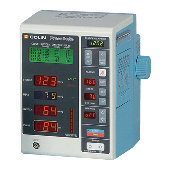
Physical Description Front Panel Functions POWER Power Switch LCD Screen CLOCK SYSTOLIC DIASTOLIC PULSE (mmhg) (mmhg) (bpm) 07:00 Controls the AC or selected Displays data for previous four (4) 10:30 battery power to the monitor measurements; maximum of 400 lines OFF/STANDBY of memory can be scrolled. -
Page 10: Rear Panel Functions
Rear Panel Functions Print ON/OFF Switch Grounding Terminal PRINT In the "ON" position, the printer prints after every measurement and upon alarm violations. In the AC SOURCE "OFF" position, the unit only prints A/C Power Cord Receptacle upon alarm violations. PRINT MODE FUSE 1A SLOW BLOW Print Mode Switch... -
Page 11: Diagrams
3. REPLACE WITH SAME NEONATAL TYPE & RATING OF TYPE B DISPLAY BATTERY. (12v 2.3 Ah) DISPLAY ASSEMBLED BY COLIN MEDICAL INSTRUMENTS CORP., SAN ANTONIO, SWITCH TX, USA. USING DOMESTIC AND IMPORTED PARTS. LR83689 PRINT STD C22.2 NO. 125 PRINT... - Page 12 POWER 120V. ~ 60 Hz 0.3A NEONATAL TYPE & RATING OF BATTERY. TYPE B (12v 2.3 Ah) DISPLAY DISPLAY ASSEMBLED BY COLIN MEDICAL INSTRUMENTS CORP., SAN ANTONIO, SWITCH TX, USA. USING DOMESTIC AND IMPORTED PARTS. LR83689 PRINT STD C22.2 NO. 125...
- Page 13 POWER 120V. ~ 60 Hz 0.3A NEONATAL 3. REPLACE WITH SAME TYPE B TYPE & RATING OF DISPLAY PRINT DATA BATTERY. ASSEMBLED BY COLIN MEDICAL (12v 2.3 Ah) INSTRUMENTS CORP., SAN ANTONIO, SWITCH TX, USA. USING DOMESTIC AND INTERFACE IMPORTED PARTS. LR83689 PRINT STD C22.2 NO.
- Page 14 Front Panel 8800SAT/SATP PULSE AMPLITUDE ADULT/NEONATAL INDICATOR SCREEN MODE DISPLAY CLOCK/ELAPSED TIME DISPLAY LIST C L O C K / E L A P S E D Press-Mate PAPER FEED CLOCKSYSTOLICDIASTOLICPULSE AMBIENT (mmHg) (mmHg) (bpm) LIGHT 07:00 120 75 68 BATTERY LEVEL DETECTOR 10:30 122 71 68...
- Page 15 TYPE & RATING OF PRINT BATTERY. TYPE B (12v 2.3 Ah) SWITCH DISPLAY ASSEMBLED BY COLIN MEDICAL INSTRUMENTS CORP., SAN ANTONIO, TX, USA. USING DOMESTIC AND IMPORTED PARTS. L R 8 3 6 8 9 PRINT STD C22.2 NO. 125...
-
Page 16: Section 3 -- Installation
Installation Precautionary Statements • The Press-Mate's accuracy is dependent upon the application of the proper cuff and hose. • The monitor will not operate efficiently on patients who are experiencing convulsions or tremors. • If the cuff is not at heart level, the reading may be affected by hydrostatic effect. •... -
Page 17: Installation
® • Use only Nellcor oxygen transducers. Use of other oxygen transducers may cause improper oximeter performance. • Inaccurate measurements may be caused by incorrect sensor application or use; significant levels of dysfunctional hemoglobin or intravascular dyes; exposure to excessive illumination, such as surgical lamps, bilirubin lamps, fluorescent lights, infrared head lamps or direct sunlight;... -
Page 18: Stand Assembly
Press the power switch located in the lower right hand corner of the front panel of the monitor. All LED's will light up and "SELF-TEST" and the Press-Mate's current software revision will be displayed on the LCD list screen. There will be three (3) beeping sounds at this time. The blood pressure measurement operation can be started when "0"... -
Page 19: Cuff Placement
Cuff Placement Proper cuff size and placement is essential to assure accurate blood pressure measurement. The American Heart Association recommends cuff sizes should be at a length to width ratio of about 2:1, ensuring that if the bladder width is 40 percent the arm circumference, the bladder length will encircle 80 percent of the arm. - Page 20 Wrap the cuff in the following way: Wrap the cuff snugly with room between the cuff and the arm for two fingers. If the cuff is wrapped too loose, it cannot be inflated properly and there may be errors in measured values. It is best to wrap a bare arm;...
-
Page 21: Section 4 -- Special Control Settings
Special Control Settings Setting the Blood Pressure Measurement Interval Measurement is initiated automatically at timed intervals by pressing the “INTERVAL” switch. INTERVAL Press the switch to display a value on the “INTERVAL” display sections. INTERVAL Settings (minutes): OFF, CON, 1, 2, 2.5, 3, 5, 10, 15, 20, 30, 45, 60, 90, 120, 180 S T A R T When the interval is selected, cuff inflation will begin immediately after depressing the button. -
Page 22: Alarms
Alarms Audible The monitor will sound an alarm when parameters set for systolic, mean, diastolic pressures, or pulse rate are violated. The audible alarm is a high-pitched tone that sounds at one second intervals. To silence the alarm press the switch. -
Page 23: Setting The Clock
Setting Alarm Limits Press the “Alarm Set” switch. The LCD display shows the menu and the cursor flashes at “SYS”. Set the upper and lower limits for “SYS”. Press the switch to set the upper limits (the value cannot be set below the lower limit on the alarm setting). -
Page 24: Alarm On/Off
Alarm ON/OFF S T A R T Press the switch until the cursor reaches the alarm buzzer. When alarm is set to “ON”, the alarm S T O P tone will sound continuously until the switch is pressed. The alarm tone is preset to “ON” at the time of shipment from the factory. -
Page 25: Alarm Bp
6. Turn the Press-Mate ON, the monitor will automatically enter the Hemodynamic mode. Note: If the monitor asks for a Pass Word, contact COLIN's Technical Service Dept. at 800-829 NIBP for further instructions. The Pass Word is initially input at COLIN during manufacturing, and should not be asked for again unless the internal RAM (service menu test interval 5) has been completed. - Page 26 Upon activation, the LCD will display the following: Directional Message HD MODE DIRECTIONS USE LIST - TO SELECT USE SET TO ENTER Press SET to continue Screen #1 As this message shows, you must choose a selection by pressing the LIST ↑ ↑ and ↓ ↓ buttons to move the cursor, then press SET to enable that selection.
- Page 27 If a program is selected, the LCD will display the program of choice, its total running time and then await the pressing of the SET button to begin the program. → → PROGRAM TOTAL TIME: 4.00 HRS Press SET to begin Screen #3 If MODIFY/READ PROGRAM is selected, the LCD will then display the Modify Program screen: MODIFY / READ PROGRAM...
- Page 28 After you have completed viewing or making modifications, the LCD will then display: MODIFY / READ SCREEN SELECT PROGR SCREEN RUN PROGRAM EXIT W/O CHANGES Screen #5 If "MODIFY/READ SCREEN" is selected, the monitor will return to Screen #4. If the "SELECT PROGR" screen is selected, the monitor will return to Screen #2.
-
Page 29: Printer Function
4.11 Printer Function Models 8800P, 8800GP, 8800FP, 8800SATP With the “PRINT” switch on the rear panel in the “ON” position, the monitor will automatically print after each blood pressure measurement. If you prefer, you may cancel this feature by setting the printer select switch on the rear panel to “OFF”. -
Page 30: Loading Paper
4.12 Loading Paper Figure 4.4 Figure 4.5 Figure 4.6 Figure 4.7 1. Press the power switch “ON”. 2. Set the printer switch on the rear panel “ON”. 3. Push the right end of the handle to expose it (Figure 4.4). 4. -
Page 31: Section 5 -- Special Features
Clock/Elapsed Time Meter COLIN’S clock is a smart clock. Interval cycling of blood pressure measurements is coordinated with logical clock time. For example, during 15 minute measurement intervals that begin at 10:07, the next measurement will be at 10:15, then 10:30, 10:45, and so on. -
Page 32: Quick Systolic - Consecutive Measurements
To use the Press-Mate on neonatal patients, follow these guidelines: 1. Set the rear panel MEASUREMENT MODE switch to 'NEONATE". 2. Connect the green colored pressure hose and COLIN's disposable neonate blood pressure cuff to the monitor and patient. 3. Standard initial inflation pressure in the neonatal mode is 120mmHg. -
Page 33: Operation: Genius
After the value has been read by the Press-Mate, the Genius is ready for another measurement. NOTE: COLIN has installed an Anti-Theft feature in the Genius with Software version 2.0 or lower. If a temperature measurement is attempted without the previous measurement being transmitted to the Press-Mate, the Genius will display "bP"... - Page 34 Genius: a. CAL: In the CAL mode, the display will indicate the absolute temperature without adjustment. This mode should only be used for calibration purposes. Call your COLIN Service Representative for calibration procedures. b. ORAL: The tympanic temperature is adjusted to display an oral temperature equivalent.
-
Page 35: Operation: Filac
Operation: FILAC Oral Temperatures 1. Place the probe tip firmly in the sublingual pocket on the left or right side of the frenulum linguae the vertical fold of tissue in the middle of the tongue. Aim the probe tip toward the back of the mouth. NOTE: Accurate temperatures can only be obtained in the "heat pocket"... -
Page 36: Battery Care, Installation And Removal
Normal/Direct Read Mode Selection The F-2000 may be used in the Normal (NORM) or Direct (DIR) mode. The mode selected is determined by the position of the switch next to the battery compartment door on the back of the thermometer. NORM: The F-2000 measures temperatures in approximately 30 to 35 seconds using a "predictive method". -
Page 37: Procedure For Changing The Press-Mate Battery Charging Circuit
Procedure for Changing the Press-Mate Battery Charging Circuit NOTE: THE PROCEDURE SHOULD ONLY BE APPLIED TO MONITORS THAT ARE BEING USED IN AREAS OF THE HOSPITAL THAT CONTINUOUSLY USE THE MONITOR ON BATTERY POWER. IF THIS CHANGE IS APPLIED TO THOSE UNITS THAT ARE NOT CONTINUOUSLY USED ON BATTERY POWER, THE OVERALL 2 YEAR EXPECTED LIFE MAY BE SHORTENED DUE TO THE CONTINUED CYCLIC CHARGING RATE. - Page 38 S6 S6 Rear Case Remove the S6 and S8 screws. Lift the rear case away from the chassis, making sure to Battery disconnect the battery connector. Connector When applying rear case, make sure the battery felt is located between the front case and chassis, as the rear case is lowered into position.
-
Page 39: Section 6 -- Theory Of Operation For Press-Mate, Genius And Filac
The continuous cuff deflation technique is very comfortable for the patient, because the pressure in the cuff is being constantly relieved after the initial cuff inflation. Furthermore, COLIN has implemented algorithms in its oscillometric blood pressure monitors, which adjust the cuff deflation rate according to the patients heart rate. -
Page 40: Pneumatic System
Pneumatic System L Tube Bleed Valve L Tube Main CPU Dump Valve Board Air Tube C Air Tube B Over Pressure Air Manifold Transducer Switch Air Tube A Pump L Tube Cuff Figure 6.1 Press-Mate Pneumatic System The Press-Mate determines blood pressure using the oscillometric method. Measurements are taken during cuff deflation, which is controlled by a micro-computer. -
Page 41: Main Pcb
Analog-to Digital Converter (U30). U30 then translates this signal into a digital format for its transmission to U12 and U14. The Main CPU (U12) with the use of COLIN's proprietary algorithms, determines systolic, mean, diastolic, and pulse rate values. Once the Main CPU has determined these values, this information is then loaded in the RAM (U10) for switching by the I/O controller (U23) display board via connector (CN1). -
Page 42: Display Pcb
The Main PCB is connected to other major components in the Press-Mate via the following connectors: CN1 - Connects the Main PCB with the Display Board CN2 - Connects the Main PCB with the Power Supply CN3 - Connects the Main PCB with the Pump and Valve Assemblies CN4 - Connects the Main PCB with the Printer CN6 - Main PCB RS232 Connection CN10 - Connects the Main PCB to the Alarm Buzzer... -
Page 43: Theory Of Infrared Transmission, Ms Series
Theory of Infrared Transmission, MS Series The Sherwood IMS Genius communicates the results of a temperature measurement via an infrared communication link. The Genius contains an infrared transmission light-emitting diode (LED), which sends optical impulses to the Temp-Mate. A semi-conductor optical detector in the Temp-Mate receives the optical impulses and converts them to electrical impulses. -
Page 44: How The Genius Derives The Temperature Of An Infrared Target
How the Genius Derives the Temperature of an Infrared Target 1. Genius uses an infrared sensing device called a "thermopile detector" to measure infrared emissions from a target such as the tympanic membrane in the ear. 2. The thermopile is best described as a series of thermocouples, arranged around a blackened, "heat collecting" surface. -
Page 45: Sleep Mode Compared To, Or Versus, Wake Mode
2. It keeps approximately one second's worth of temperature scans stored in a buffer. This buffer is continually refreshed. Because only the most recent second of data is held in the buffer, it is very unlikely that the unit would store a "false peak," such as would be seen when passing the probe tip over a hot cup of coffee. 3. -
Page 46: Power Supply
6.14 Power Supply 9 Volt Alkaline Battery, 650 mah Out: +5 Volts Current Sleep Mode - Approximately 25 µA Consumption: Wake Mode - Approximately 7.5 mA Battery Life: 6 to 8 months (average 600 temps / month) 6.15 The +5 Volt Supply 1. -
Page 47: Eeprom
6.18 EEPROM 1. The Genius uses a 93CS46 EEPROM, which contains special internal data protection logic to minimize the possibility of data loss. 2. The Genius calibration table is contained in EEPROM memory (U2). 3. US is powered directly by one of the "high current" I/O pins on the CPU and is normally off. 4. -
Page 48: Front End Switch
6.22 Front End Switch In order to reduce current consumption and increase battery life, the F-2000 leaves the front-end circuitry off except when it is time to take a reading. The "switch" that controls this is Q1. When the MCU needs to take a reading, it biases Q1, bringing the front-end ground to true ground and applying power to U1, U2, and their associated components. -
Page 49: Calibration Self-Check Circuitry
6.25 Calibration Self-Check Circuitry The F-2000 performs a two-point calibration self-check every time it is turned on. This is accomplished under a microcontroller program control by biasing the FET switches Q9 and Q10 in turn, switching precision calibration resistances into the F-2000 front-end circuitry. Q10 switches in the "Low Cal" resistance value represents 89.5ºF (31.9ºC). -
Page 50: Section 7 -- Calibration Verification For Press-Mate, Genius And Filac
Then press the “START/STOP” switch to begin the test. As each test is completed, progress through the menu to subsequent tests by pressing the INTERVAL up “∆“and down “∇“ switches. NOTE: If adjustments are needed to bring the test values into calibration, contact COLIN’S Technical Services Department for assistance. -
Page 51: Test Menu
Test Menu Interval Test Name Description Alarm buzzer ON/OFF, CONT, TIME Alarm buzzer ON/OFF, Continued, Adjust Time, ADJUST, INITIAL INFLATION Date and Initial Inflation Controls all Smart ADJUST Features if Applicable Safety Timer Test Tests the “Watch Dog Timer Circuit” Telemeter Checker Mode TRM Test Tests all rear panel switches (Adult/Neonatal,... -
Page 52: Testing Sequence
7.3 Testing Sequence The manufacturer recommends that the user carry out the test sequence in the order presented in the following subparagraphs, although skipping to a specific test is possible. For the interval order, the tests are found in, see Section 7.2. - Page 53 Rear Panel Switch Test Push the START/STOP switch to start the test. Each LED digit will show the rear panel switch settings as follows (“0” = OFF; “1” = ON). The display of the rear switch settings can be found on the DIASTOLIC window of the model 8800MS and the MEAN window of all other Press-Mate models.
- Page 54 VER#, All RAM Clear Test Use this test to verify the current software version number and clear the RAM contents. Remember that when the RAM is cleared, the previously set ALARM SYSTOLIC settings are also cleared. This means that after the “ALL RAM CLEAR”...
- Page 55 Initial Deflation Test In this test, the Press-Mate will inflate the 220 cc dummy cuff to about 180 mmHg, then slowly deflate the cuff while calculating the operating parameters as follows: COUNTS Time from the beginning of the deflation period to the point at which the cuff pressure is 25 mmHg below the initial inflated cuff pressure (180 mmHg).
- Page 56 Display Test a. Push the START/STOP switch to start the test. b. Half of all the display segments will operate. Push the START/STOP switch again to check the remaining display segments. c. After completing this test, select another test by pushing the INTERVAL UP key. Calibration Mode Test (Use apparatus shown in Figure 7.3) In this test, the user can verify the accuracy of the internal pressure sensor by introducing a known air pressure...
- Page 57 Electrical Circuit Overpressure Test (Use apparatus shown in Figure 7.3) a. Make sure that there is nothing connected to the cuff connector. b. Press the START/STOP switch to start the test c. The unit will begin to pump air out of the cuff connector. d.
- Page 58 LCD screen. When nearing the Overpressure point, increase the pressure as slowly as possible to get an accurate reading. Recommendation from COLIN, insert a large syringe into the tubing and then use the syringe for a gradual increase in pressure to help from spiking the pressure making it difficult to recognize the actual pressure upon Overpressure detection of the unit.
-
Page 59: Calibration Verification: Genius
7.4 Calibration Verification: Genius The Genius is constructed using solid-state electronics with surface-mount components for durability and reliability. The only moving part in the probe is the RELEASE button assembly, which provides for long service life. There are no electronic adjustments available to the biomedical engineer. All calibration is performed digitally and is stored in nonvolatile EEPROM. -
Page 60: Using The 3000A-Cl Electronic Calibrator
7.8 Using the 3000A-CL Electronic Calibrator Since a complete calibrator Operation Manual is shipped with every 3000A-CL calibrator, the information it contains is not repeated here. However, before attempting to use a 3000A-CL calibrator, and, before attempting to adjust calibration offset, please read the instruction manual carefully. Pay careful attention to the special section at the end of the instructions, entitled: “Do’s and Don’t’s of Using the 3000A-CL Electronic Calibrator.”... -
Page 61: Field Recalibration Procedure
8. Adjust VR1 to obtain a reading of 100 mv, +/- 5 mv on the DVM. 9. Adjust the decade box to 4746 ohms, +/- 2 ohms. Record the voltage now observed on the DVM. 10. Connect the DVM + lead to T1-4. 11. -
Page 62: Section 8 -- Troubleshooting
Are all cuff and cuff hose fittings secure and without leaks? Are error codes displayed Cuff will not inflate on the LCD screen on the front of the unit? If so, call COLIN Technical Services at 800-829-8100. If the displayed cuff pressure is increasing rapidly but the cuff is still not inflating, check to see if the cuff hose is crimped or bent. -
Page 63: Troubleshooting - Possible Causes And Remedies
5-7 mmHg lower systolic and 5-7mmHg higher diastolic value than an oscillometric measurement. Monitor failures- Colin monitors offer the user a source of displayed information to help them with monitor failures. These messages include advisory, caution, and error codes. The following information may be displayed. Messages- •... - Page 64 E01 and E02 RAM/ROM Failure- These messages alert the user to failure of the self test of the unit. If • one of these messages appear, restart the unit and if the message reappears the unit must be serviced by the appropriate personnel. •...
-
Page 65: Error Codes
Error Codes — Blood Pressure Monitor Probable Cause Error Code Displayed Message Description "E01 Internal Error" RAM failure "E02 Internal Error" ROM failure "E03 Cuff Disconnect" The pressure was less than 10 Check connection between the mmHg more than 10 seconds unit and air hose, and cuff. -
Page 66: Problems With The Unit - Cause & Solution
Problems with the unit – Cause & Solution As problems occur with the operation of the unit, you can use the following possible solutions to aid in the troubleshooting of the problem. You may be required to utilize this information in conjunction with the service calibration procedures to accurately troubleshoot the source of the problem. - Page 67 The unit seems to turn ON but the display is blank or fully lit. CAUSE SOLUTION Display switch is OFF Verify the display switch on the rear case is on. LCD ribbon Verify the ribbon cable is correctly attached. cable dislodged VR1 on main board Verify VR1 on the main board is appropriately set.
- Page 68 Front panel switches don’t work or LEDs will not light CAUSE SOLUTION Sheet switch Verify the ribbon connector from the switch to the display is defective board is connected. If you cannot feel the depression of the Or not connected switch, replace the sheet switch.
- Page 69 Unreliable readings (Inaccurate NIBP) Continued CAUSE SOLUTION Unstable blood pressure Verify patient for reciprocal pulsations or respiratory alterations. Patient Physiology Patient’s pulse pressure may not be adequate for monitor to allow TBP measurements. Continue with oscillometric measurements. Calibration (NIBP) Check the calibration of the NIBP transducer Deflation Speed Check for internal leaks and deflation speed.
- Page 70 Overall Battery Life is suspect CAUSE SOLUTION Blown F1 fuse Replace defective 3A fuse. on Power supply Low/Empty Indicator Connect a DC power supply to the unit in place of the battery. failure Slowly decrease the voltage of the power supply from 14.0 volts until the “Battery Low”...
-
Page 71: Repair Notes
While repairs are in progress it is always important not only to verify operation after the repair, but to also check for the following, if you are to familiar with one of the below mentioned upgrades or kits, call Colin’s Technical... -
Page 72: Section 9 -- Illustrated Parts Listing
9.0 Illustrated Parts Listing Parts Listing: 8800 PC BOARD ID # Part # Description 0330187A Main Board 8800P 0330244A Main Board 8800P (Smart Features) 0330188A Main Board 8800C 0330245A Main Board 8800C (Smart Features) 0330207A Main Board 8800MSP (no Neonate) 0330206A Main Board 8800MS (no Neonate) 0310050A... - Page 73 REAR PANEL Rear Case Kits are as follows: Rear Case C/TC (8800C or 8800TC) Basic unit, no printer, no ON/OFF switch Rear Case C PS (8800C or 8800TC) Basic unit, no printer, w/ON/OFF switch Rear Case P/TP (8800P/TP/MSP) Basic unit, w/printer, no ON/OFF switch Rear Case P PS (8800P/TP/MSP) Basic unit, w/printer, w/ON/OFF switch Rear Case MS (8800T wo/neo switch)
- Page 74 Part # Description XC2110394C Sub Chassis 6820001A Printer 8800,BX-5 X2120531B Printer Stand X2120534C Photo Interrupter Bracket 0780002A Photo Interrupter X4240012A Roller Guide XC6140390A Overpressure Switch 3210021B Paper Box X3210022A Paper Box Base XC2110266B P, Plate Paper Guide 0200023A Pump w/Pump Nut XC2120861A Rt.
-
Page 75: Accessory Parts List: 8800
Accessory Parts List: 8800 COLIN MEDICAL INSTRUMENTS hours of operation are 8 a.m. to 6 p.m. (Central Standard Time), Monday through Friday. Call us for pricing or additional information at 800-829-NIBP (6427). Description Order # Description Order # Order #... -
Page 76: Parts List: 8800Ms, 8000Ir, 8000N
Parts List: 8000MS, 8000IR, 8000N ID # Part # Description 3200417A Base Case 3200418A Right Case 3200419A Left Case 3200419A Probe Cover Case 3200420A IR Detector Plate 3200422A Door 3200423A Door Hinge Right 3200424A Door Hinge Left 3200425A Genius Latch 3200426A Latch Guide 3200427A... -
Page 77: Parts List: Filac
Parts List: FILAC ID # Part # Description 7774-005909 Printed Circuit Board Assembly 7774-101971 (2) "AA" Battery 7774-105717 Normal/Direct Mode Switch Assembly 7774-701077 Touch Panel 7774-178003 Mylar Overlabel 7774-400233 (2) No. 6 Plain Washer 7774-303213 (3) No. 4 - 10 x 1/4" Self Tap Screw 7774-303783 (2) No. -
Page 78: Section 10 -- Schematics
10.0 Schematics 10.1 Block Diagram: 8800 10-1 back to contents page... -
Page 79: Main Pcb
Diagram of 8800 (without Smart Features) Bleed Valve Dump Valve Main PCB Transducer Manifold Pump Over Pressure Switch Cuff Diagram of 8800 (with Smart Features) Reservoir Orifice Solenoid Main PCB Transducer Manifold Over Pressure Sensor Bleed Valve Dump Valve Cuff Pump 10-2 back to contents page... - Page 80 10.2 Block Diagram: Genius V REF TPILE XTAL1 XTAL2 SPEAKER INTO THERM WAKE-UP EEPROM THERM POWER SWITCHES SWITCH +5V REG -5V REG IR LED BATTERY 10-3 back to contents page...
-
Page 81: Power Supply Pcb
11.0 Specifications for Press-Mate, Genius and FILAC 11.1 Environmental Requirements: 8800 Power Supply 120 Volts AC Power Consumption 33 VA Operating Temperature 10 to 40 ºC Operating Humidity 15 to 95% Storage Temperature -20 to 70 ºC Storage Humidity 5 to 95% Nominal Life 6 years 11.2 Functional Specifications... -
Page 82: Output Terminal Dsub-15
11.4 Output Terminal DSUB-15 PIN NO. F.GND Tx (RS232C level output) Rx (RS232C level output) RTS (RS232C level output) CTS (RS232C level output) +5 V Tx (TTL output) Rx (TTL output) RTS (TTL output) CTS (TTL output) +12 V ON/OFF R/B (TTL) 11.5 Physical Specifications Measurement Method... -
Page 83: Standard Accessories
11.6 Standard Accessories Disposable Adult Cuff Adult Cuff (12 cm in width) 3.5 m pressure hose Paper Roll (for units with printers) Paper Shaft (for units with printers) AC-power cord Boxes Patient Pack Genius Probe Covers Rolling Stand Dust Cover Operations Manual 11.7 Communication Specifications Asynchronous... - Page 84 ALARM MARK Over higher limit - ">" = ASCII code 3 E Under lower limit - "<" = ASCII code 3 C Without alarm - ASCI code 2 Ø SYS, MEAN, DIA, PR – Each value consists of 3 bytes in ASCII code. YEAR, MONTH, DAY, HOUR, TIME –...
-
Page 85: Specifications: Genius
11.8 Specifications: Genius Accuracy: ±0.2ºF (±0.1ºC), 96ºF - 102ºF Other points as specified by A.S.T.M Temperature Range: 60ºF to 110ºF (15.5ºC to 43.3ºC), ºC or ºF Ambient Temperature Operating Range: 60ºF to 104ºF (15.5ºC to 40ºC) Storage Temperature Range: -4ºF to 122ºF (-20ºC to 50ºC) Response Time: Approximately 1 to 2 seconds Primary Mode: Tympanic Resolution: 0.1ºC (0.1ºF) displayed on LCD... -
Page 86: Specifications: Filac
11.9 Specifications: FILAC Weight: Approximately 19 ounces (excluding probe) Dimensions: Approximately 2 3/4"H x 3/14"W x 6 1/16"L (excluding probe) Measurement Range: 90ºC to 110ºF (32º to 43ºC) Display Range: ± 0.1ºF or ±0.1ºC Ambient Operating Temperature: 60º to 90ºF (15.6º to 32ºC) Accuracy: Meets or exceeds A.S.T.M. -
Page 87: Section 12 -- Press-Mate 8800Sat/Satp
12.0 Press-Mate 8800SAT/SATP 12.1 Operations Taking a Reading 1. Once the appropriate sensor has been applied to the patient, turn the unit on. The N-20P automatically tests its circuitry and lights the entire display. If a problem is detected, an error message is displayed. NOTE: During operation, the constant pitch beeper sounds once for each pulse, and the pulse amplitude indicator reflects pulse strength at the sensor site. - Page 88 3. If paper remains jammed between the print head and printer, press the ADV button; the jammed paper may work its way out. If the paper remains jammed, and the printer drive does not advance the paper, manually advance the drive gear on the side of the printer to free the paper. 4.
- Page 89 Replacing the Real-Time Clock (RTC) Battery The socket for the RTC battery (BTI) is located on the auxiliary PCB at grid location 5D. Typical life of the clock battery is 5 years. Caution: After replacing and RTC battery, switch the instrument, on then immediately switch it off; this action will prevent possible damage to the RTC voltage circuit.
- Page 90 Replacing the DB-9 Connector 1. Disassemble the N-20P; the connector is on the main PCB at grid location 3A. 2. Using a low-power soldering iron, unsolder the connector from the PCB and remove it. Save all Teflon tubing, ferrite blocks, and insulating materials for the replacement connector. 3.
-
Page 91: Theory Of Operation For N-20P
12.2 Theory of Operation for N-20P Overview The N-20P is based on the principles of spectrophotometry and optical plethysmography. Optical plethsymography uses light absorption technology to reproduce wave forms produced by pulsatile blood. The changes that occur in the absorption of light due to vascular bed changes are reproduced by the pulse oximeter as plethysmographic wave forms. - Page 92 Overview This section provides a detailed explanation of N-20P operation using block diagrams and circuit schematics. The N-20P consists of three main components: 1. The N020P main PCB schematic diagram. 2. The N-20P auxiliary PCB schematic diagram. 3. The N-20P flex circuit schematic diagram. The relationship between these components and their interconnection is illustrated in the overall block diagram.
- Page 93 Printer Control Block Diagram Printer circuitry is divided into two subsections: the printer interface and the printer flex circuit. The printer interface circuitry is present on all models, but is disabled by software in the N-20. The printer flex circuit is added when a printer is present.
- Page 94 Display and Analog Shield Assembly – this assembly connects to the main PCB by flex circuits. A metal shield shrouds the SpO2 analog circuits on the main PCB to protect them from EMI. An integrated electroluminescent backlight illuminates the display under low light conditions. The N-20P has an additional printer control board (printer flex circuit), and printer hardware.
- Page 95 Signal gain – The separated LED signals are amplified so that their current levels are within the A/D converter's acceptable range. The signals are filtered to improve the signal-to-noise ratio, and clamped to a reference voltage. AC ranging – DC offset is eliminated from each LED signal. An analog switch sets the mean signal value to the mean of the A/D converter range, and the AC modulation is superimposed on that DC level.
- Page 96 LED Drive Circuit The IR and red LEDs are separately controlled with their drives currents multiplexed over two shared wires. Current to the IR LED is in the range of 4.3-50.0 mA; and, current to the red LED is in the range of 6.5-75.0 mA.
- Page 97 U6D, a single-pole-single-throw (SPST) analog switch, is controlled by the same line that controls the on/off pulsing of the LEDs. When either of the LEDs are on (the line is low and the switch is closed) U35 is used as a non-inverting amplifier.
- Page 98 AC Ranging In order to achieve a specified level of oxygen saturation measurement and to still use a standard type combined CPU and A/D converter, the DC offset is subtracted from each signal. Because the DC portion of the signal can be on the order of one thousand times the AC modulation, 16 bits of A/D conversion would otherwise be required to accurately compare the IR and red modulations between the combined AC and DC signals.
- Page 99 • Display Control – A high-visibility display provides oxygen saturation and pulse rate values. An ambient light sensor responds to low light conditions and turns on the display backlight. • User Controls – A measure button and a battery-check button. The measure button signals the power control circuit to switch on the power supply.
- Page 100 When the power supply is first switched on by the power control circuit, the reset generation circuit holds the CPU RESET pin low for at least 20 ms, then allows the internal pull-up resistor to bring it high; this assures a good CPU reset.
- Page 101 Address Decoding The CPU has a 64K byte address range of 0-FFFF. RAM, EPROM, and I/O ports share this space. The address decoding circuit splits up this space and output enable lines to the RAM, EPROM, and I/O ports. U30A generates the static RAMs active low enable signal, RAMEN. When address lines A13, A14, A15 are all high, U30As output goes low, enabling the RAM.
- Page 102 Input Port U16 is the input port external to the CPU. The logic levels on the inputs (pins D1-D8) are output to the CPU via the AD bus while EXINEN is strobed low. All of the user control buttons are input via U16. Also, the battery type is sensed via U16;...
- Page 103 Audio Output BZ1, a piezo ceramic sounder, is the audio output device. Due to its low drive current of 2 mA maximum, no drive circuitry is needed and is driven directly from the external output port. It is differentially driven with 2 square waves 180 degrees out of phase.
- Page 104 Control Conditioning Circuit The CPU generates a 400 µs low pulse rate train at a 160 Hz rate on signal DISP PHASE. Half of U34 takes DISP PHASE as an input and creates DISP POL as an 80 Hz 50% duty cycle square wave. A CPU reset initializes DISP POL low when any CPU reset occurs so the software knows the initial state.
- Page 105 Power Supply/Power Control Circuitry Power supply circuitry is located on the auxiliary PCB and consist of the following subsections: • Batteries – Four 1.5 V alkaline "C" size batteries provide 4-6 VDC power. • Power control circuitry – Power control circuitry is connected to the batteries. It senses any press of the measure button and switches on the power supplies.
- Page 106 Power Control Circuitry The power control circuit consists of U21 and its associated components. U21 is a D flip/flop with asynchronous preset and clear; only the preset and clear are used. Power is applied to U21 via CR11 whenever batteries are installed. CR11 provides protection for U21 if the batteries are installed with reverse polarity.
- Page 107 Raw Power Supplies The input to the raw power supplies is VCC, which is a switched-capacitor voltage converter operating in separate multiply and invert modes in conjunction with supporting circuitry. U23 inverts Vcc and outputs raw -5 V. Raw 10 V is derived by voltage doubling Vcc with CR14, CR19, CR20, and CR78. Raw 12 V is derived by voltage tripling Vcc with CR15, Q8, Q9, C96, C81, R119, and R120.
- Page 108 Battery Voltage The analog input voltage range of the CPU is 0-5 VDC. Because the battery voltage may be as high as 6.2 V, R69 and R70 form a voltage divider to decrease the measured battery voltage to a usable level. The gain is 0.75; thus, if the battery voltage was 6 V, then the voltage of BAT VOLT would be 6 x 0.75 which equals 4.5 V.
- Page 109 N-20P only Main PCB AUX PCB Printer Printer Printer Microprocessor Circuit Interface (N-20P only) (N-20P only) D/D User Push Buttons Figure 12.7 Printer Control Block Diagram Printer Interface Circuit The following is a description of the printer interface circuitry found on all N-20P auxiliary PCBs. The CPU reads the PR PRESENT signal to determine if a printer is installed.
-
Page 110: Calibration Verification For N-10P
The position of the print head is sensed by the signal PR HOME. Whenever the print head is not in the home position, a switch in the printer closes, shorting PR HOME to switched ground. Whenever the print head is in the home position, the switch opens, allowing R118 to pull PR HOME high. - Page 111 Power-On Self Test (POST) When an N-20P is switched on, a sequence of diagnostic tests are run that examine the instruments electronics and display functions. This power-up self-test consists of the following events: Immediately after power is switched on, the instrument simultaneously: •...
- Page 112 CAUTION: If a sensor is attached, remove it prior to running the following test. 1. Switch off the N-20P; open the battery door and remove the batteries. 2. Set the power supply's voltage to 5 VDC, and connect the supply to the battery clips of the N-20P – ensure that polarity is correct.
- Page 113 Printer Test The SRC-1 can be used to test the operation of the N-20P printer and the printer's user-control buttons. When an SRC-1 is plugged into the DB-9 connector, the N20P does not respond to button presses during POST; however, it does acknowledge any button press with an immediate beep and the following play codes: Button Press Display measure...
-
Page 114: Troubleshooting
12.4 Troubleshooting WARNING: Disassembly of the N-20P can expose service personnel to potentially hazardous voltages. For protection of service personnel and patients, the procedures must be performed as described in this section. Repair and testing must only be performed by qualified service personnel. Improper repair and/or adjustment may compromise patient safety or the accuracy of the instrument. - Page 115 Removing the Covers Figure 12.9 N-20P Covers with the PCB and Display Assembly 1. Remove screw cap (3), and loosen the captive screw (31) which secures the rear battery cover (15). 2. Separate the front cover (16) from the rear cover by wedging a thin flathead screw driver between the covers at the base of the instrument and slowly prying them apart.
- Page 116 Removing the PCBs and Display Assembly Figure 12.10 Main, Auxiliary, and Display PCB Assembly 1. Remove the measure button (6) from the main PCB. 2. Remove the entire PCB/Taliq display assembly from the rear battery cover by tilting opposite the battery check button (5).
- Page 117 N-20P Disassembly Procedure 1. Remove the paper door (20) and any printer paper by firmly grasping the paper roll, and pulling the roll outward from the printer. 2. See "Disassembly procedure for removal of covers, PCBs, and the display assembly". Disassembling the Printer/Flex Circuit Assembly Figure 12.11 Printer and Flex Circuit installation 1.
- Page 118 Troubleshooting Guide This section discusses potential symptoms, possible causes, and actions for their resolution. Should this trouble- shooting guide fail to address the symptoms evident in a particular N-20P, please contact Nellcor Technical Services Department or a local Nellcor representative for assistance. If the N-20P does not perform as expected: •...
- Page 119 CAUSE 3: Perfusion may be too low. ACTION 3: Check patient status. Test the instrument on someone else, or try another type of sensor. The N-20P will not make a measurement if perfusion is inadequate. CAUSE 4: Foreign material on the sensor LEDs or photodetector may be affecting performance. ACTION 4: Clean the test area and ensure that nothing blocks the sensor site.
- Page 120 ____________ SYMPTOM 6: Err followed by a number appears on the display. CAUSE 1: See "Error Codes" in this manual. ACTION 1: Record the number that is displayed. ____________ SYMPTOM 7: Time or date is incorrect. CAUSE 1: The real-time clock battery may be exhausted. ACTION 1: Replace the RTC battery.
-
Page 121: Parts List
12.5 Parts List N-20P Spare Parts. To order replacement parts, contact Nellcor Puritan Bennett's Technical Service Department at 1-800-NELLCOR and order by part number. Item Designator Description Battery switch (auxiliary PCB) 630106 Battery holder (auxiliary PCB) 901582 Battery, lithium (auxiliary PCB) 640112 Bracket, printer, hold-down 203133... - Page 122 Item Designator Description Screw, plastite 871031 Sensor lock 022943 Sensor shroud 022944 Spacer 023452 Stiffener, printer button 023131 Tap, foam (.88" x .38") 023300 Transducer, audio, piezo ceramic 691230 12-36 back to contents page...
-
Page 123: Specifications For N-20P
12.7 Specifications for N-20P Components • N-20P pulse oximeter • Four alkaline "C" size batteries • DURASENSOR ® DS-100A oxygen transducer 2 OXISENSOR D-25L oxygen transducers • • EC-4 sensor extension cable • Protective rubber boot (includes shoulder strap and hand strap) •... - Page 124 Printer Output When activated by the printer ON button, the N-20Ps output shows: date, time, SpO , and pulse rate (in spot check mode), with space provided for writing in patient identification. The thermal paper printout measures roughly 40 mm (=1.6 in.) by 100 mm (=4.0 in.) in size. If the N-20P is in spot check mode and the printer is turned on any time during a measurement or after a measurement is taken and before the N-20P powers down, the printer will catch up and print a complete record of the measurements recorded up to the current moment.
- Page 125 Sensor Types SENSOR Model Patient Size OXISENSOR oxygen transducers: N-25 <3 or >40 kg I-20 1-20 kg D-20 10-50 kg D-25, D-25L >30 kg R-15 >50 kg ® OXIBAND oxygen transducers: OXI-A/N <3 or >50 kg OXI-P/I <3 - 40 kg NELLCOR reflecting oxygen transducer: RS-10 >40 kg...
Need help?
Do you have a question about the Press-Mate 8800 Series and is the answer not in the manual?
Questions and answers