Table of Contents
Advertisement
Quick Links
The way PC-based instrumentation should be
DI-1000TC
Instrumentation Modules for Temperature Measurements
User's Manual
Manual Revision M
Copyright © 2012 by DATAQ Instruments, Inc. The Information contained herein is the exclusive property of
DATAQ Instruments, Inc., except as otherwise indicated and shall not be reproduced, transmitted, transcribed, stored
in a retrieval system, or translated into any human or computer language, in any form or by any means, electronic,
mechanical, magnetic, optical, chemical, manual, or otherwise without expressed written authorization from the com-
pany. The distribution of this material outside the company may occur only as authorized by the company in writing.
DATAQ Instruments' hardware and software products are not designed to be used in the diagnosis and treatment of
humans, nor are they to be used as critical components in any life-support systems whose failure to perform can rea-
sonably be expected to cause significant injury to humans.
DATAQ, the DATAQ logo, and W
D
are registered trademarks of DATAQ Instruments, Inc. All rights reserved.
IN
AQ
241 Springside Drive
Akron, Ohio 44333, USA
Telephone: 330-668-1444
Fax: 330-666-5434
Designed and manufactured in the
United States of America
M-100774
Advertisement
Table of Contents

Subscribe to Our Youtube Channel
Related Manuals for Dataq DI-1000TC

Summary of Contents for Dataq DI-1000TC
- Page 1 The distribution of this material outside the company may occur only as authorized by the company in writing. DATAQ Instruments' hardware and software products are not designed to be used in the diagnosis and treatment of humans, nor are they to be used as critical components in any life-support systems whose failure to perform can rea- sonably be expected to cause significant injury to humans.
-
Page 3: Warranty And Service Policy
DATAQ Instruments. The only responsibility of DATAQ Instruments under this warranty is to repair or replace, at its discretion and on a free of charge basis, the defective material. -
Page 5: Table Of Contents
3. Getting Started ........................... 5 Unpacking ............................5 Applying Power to the DI-1000TC Instrument ................. 5 Connecting the DI-1000TC Instrument to your Computer ............... 5 RS-422 Interface Port Pin Out ......................6 Adapters ............................. 6 DI-1000TC Instrument Controls and Indicators ................6... -
Page 7: Introduction
0.08°C. • Portable: The DI-1000TC is provided in a small (13.81D × 10.48W × 3.81H centimeters; 5-7/16D × 4-1/8W × 1- 1/2H inches) enclosure consisting of an aluminum base and all-steel wraparound. The following provides a brief overview of the major subsystems of the DI-1000TC Series. -
Page 9: Specifications
2. Specifications Signal Connections The DI-1000TC units are provided in 4- or 8-channel versions. Each thermocouple channel features a panel- mounted, miniature spade connector, and all input channels are electrically isolated from ground and each other up to 1000VDC, or peak AC. -
Page 10: Max. Sample Rate From Expansion
DI–1000TC User Manual Max. Sample Rate from Expansion Units: 5 samples/second/channel Maximum Distance: 4,000 feet Calibration Calibration Cycle: One year Calibration Method: Calibration constants are stored within each module's EEPROM. Provided calibration soft- ware to automate calibration in the field. RS-422 Interface Supported Baud Rates: 4800, 9600 (default), 19200, 38400, 56800, 115200... -
Page 11: Getting Started
Connecting the DI-1000TC Instrument to your Computer The built-in RS-422 interface allows the DI-1000TC unit to connect to any host PC through an inexpensive adapter via an RS-232 or USB port. (All DI-1000 adapters are available through DATAQ Instruments - See below for details.) There are two identical RS-422 ports. -
Page 12: Rs-422 Interface Port Pin Out
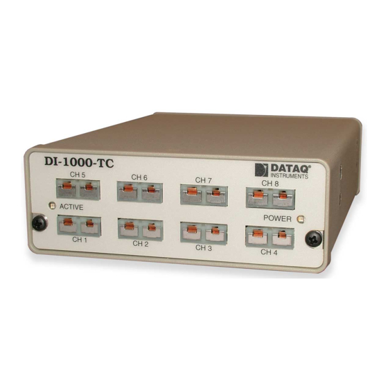
INSTRUMENTS The DI-1000TC units are provided in 4- or 8-channel versions. (The 8-channel version is pictured above.) Each channel may be configured in software to support one of seven thermocouple types: J, K, T, E, S, B, or R. Each ther- mocouple channel features a panel-mounted, miniature spade connector, and all input channels are electrically iso- lated from ground and each other up to 1000VDC, or peak AC. -
Page 13: Di-1000Tc Instrument Rear Panel
DI-1000TC Instrument Rear Panel ADDRESS: RS-422 - The built-in RS-422 interface allows the DI-1000TC unit to connect to any host PC through an inexpensive adapter via an RS-232 or USB port. (Both of these adapters are available through DATAQ Instruments.) There are two identical RS-422 ports. -
Page 14: Di-1000-Usb Installation
16. Select the Baud Rate. You should not need to change the Baud Rate - all DI-1000TC modules come pre-config- ured from the factory. If you do not enter this correctly, you may run WinDaq Lite Data Acq Setup from your WinDaq Program Group to change it. - Page 15 20. Select the Baud Rate. You should not need to change the Baud Rate - all DI-1000TC modules come pre-config- ured from the factory. If you do not enter this correctly, you may run WinDaq Lite Data Acq Setup from your WinDaq Program Group to change it.
-
Page 16: Installing Multiple Devices In A Daisy Chain
WinDaq Software to reflect the number of “Slave” devices in your network. a. Right-click on the WinDaq Lite Data Acq DI-1000TC program in the Windows startup menu. Default is Start > Programs > WinDaq > WinDaq Lite Data Acq DI-1000TC. - Page 17 DI–1000TC User Manual d. Click OK to close the Properties dialog box. Your distributed synchronous data acquisition system for thermocouple measurements is installed and ready to run. Getting Started...
-
Page 19: Module Configuration Software
DI–1000TC User Manual 4. Module Configuration Software The following is a brief overview of how to get started with the DI-1000 Configuration Software. A detailed expla- nation of the configuration software is provided in the help files within the configuration program. More than likely, you will not need to use the configuration software;... -
Page 20: Calibration
DI–1000TC User Manual The master determines that it's time to report a sample, based upon its internal clock and the data acquisition rate that was programmed for the application. The master reports its data, preceded by its address, as defined by the ModBus standard. -
Page 21: Windaq® Software
5. W Software In general, W software will operate with the DI-1000TC the same way it operates with other instruments. Use the W software manual for instructions on operation. However, there are a few differences that must be noted. Sample Rate Edit >... -
Page 22: Channel Settings
DI–1000TC User Manual Channel Settings Edit > Channel Settings: Channel Settings allows you to select the thermocouple type you are using for each channel and whether you want your data to appear in °F or °C. (°C is the default. You can toggle between °F and °C by select- ing and deselecting the "Fahrenheit"... -
Page 23: Channels
DI–1000TC User Manual Channels Edit > Channels: Channels allows you to select which channels on all of your DI-1000 devices you want to acquire data. Channels are selected by placing a check mark in the appropriate box. You will find the addresses of your devices under the "Addr"... -
Page 24: User Annotation
DI–1000TC User Manual User Annotation Edit > User Annotation: This allows you to annotate each channel to make them easily recognizable in the W screen. Highlight the channel you would like to annotate by clicking on it and then go to Edit > User Annotation. This will reveal the dialog box shown below. - Page 26 DATAQ Instruments, Inc. 241 Springside Drive Akron, Ohio 44333 Telephone: 330-668-1444 Fax: 330-666-5434 E-mail: support@dataq.com Direct Product Links (click on text to jump to page) Data Acquisition | Data Logger | Chart Recorder | Thermocouple | Oscilloscope...
Need help?
Do you have a question about the DI-1000TC and is the answer not in the manual?
Questions and answers