Table of Contents
Advertisement
Quick Links
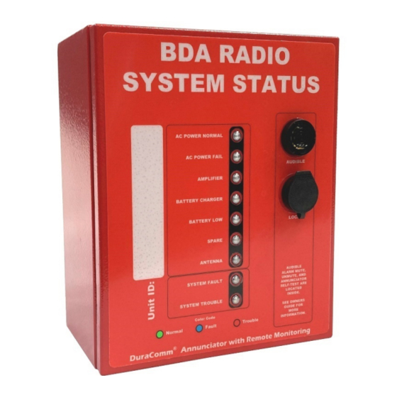
Annunciator with Remote Monitoring for BDA Emergency Radio System
*NOTE: Specifications are subject to change without notice.
Description
The DuraComm Annunciator provides visual and audible alarms at the installed location of a BDA in an Emergency In-
Building Radio system. This annunciator is designed to monitor NFPA 72 IDC Circuits and report the status to a Fire alarm
panel via Form C relay contacts. Power input is 90 to 264 VAC with an internal 12 Volt 12-hour backup battery. A loud
audible alarm will sound when a fault or trouble alarm is triggered. The Alarm can be muted until a normal condition is
restored, or until a scheduled daily unmute occurs. Audible alarm Mute, Unmute, and Self-Test buttons are located
inside for security.
It also provides remote monitoring via Ethernet. This allows the test point voltages to be monitored in relation to their
alarm points by a bar graph for each monitored input. The internal battery backup voltage is also monitored with its own
bar graph. Password-protected remote-control functions allow the system designer to set alarm voltages, manage user
logins, schedule audible alarm unmute, and many other features. Notifications of alarms can be sent via email or SNMP
traps. The DuraComm Annunciator comes with a 3-year warranty.
PSDA-MU1
Owners Guide
•
Designed to Monitor NFPA 72 IDC Circuits
•
NEMA 4, UL Listed Enclosure E333443
•
AC Power 90-264 VAC
Automatic Internal Battery Backup
•
Monitors up to 6 Closed Contacts and wiring
•
Separate 50 Ohm Antenna Fail
•
•
9 Form C Relays to Connect to Fire Alarm Panel,
Including System Fault and System Trouble
9 Bright LEDs Indicate Status
•
Audible Alarm with Inside Mute/Unmute
•
User Scheduled Unmute
•
•
Self-Test Button Inside
•
Remotely Monitor Status and More via Ethernet
•
Email and SNMP notifications
3 Year DuraComm Warranty
•
Page 1 of 47
April 20, 2022
Advertisement
Table of Contents

Summary of Contents for DuraComm PSDA-MU1
-
Page 1: Description
Description The DuraComm Annunciator provides visual and audible alarms at the installed location of a BDA in an Emergency In- Building Radio system. This annunciator is designed to monitor NFPA 72 IDC Circuits and report the status to a Fire alarm panel via Form C relay contacts. -
Page 2: Table Of Contents
Table of Contents ..................................2 Section 3: PSDA-MU1Feature List ............................4 Simplified Theory of Managing an IDC Circuit ........................5 DuraComm Annunciator Internal Operation Basics ....................... 6 DuraComm Annunciator Remote Monitoring Features ......................6 Section 1 | Important Safety Instructions ..........................8 Section 2 | Installation ................................ - Page 3 User Setup Notes ................................37 Section 5 | Remote Operation .............................. 38 Status screen ................................. 38 Status screen Notes ..............................41 Battery ................................... 41 Section 6: Internal Information ............................. 42 Annunciator Board Internal Connector Layout ......................42 Annunciator Board Jumper Options (Only Change for Non-Standard Installation)............44 Annunciator Board Test Points and LEDs ........................
-
Page 4: Section 3: Psda-Mu1Feature List
Section 3: PSDA-MU1 Feature List Firmware Product • Web Ready / Web GUI • Designed to be Compatible with NFPA 1221. Graphing of data for each analog input. • • AC-Powered Annunciator with Remote Monitoring via Bar Graphs with Alarm settings and Alarm Status Color. -
Page 5: Simplified Theory Of Managing An Idc Circuit
Simplified Theory of Managing an IDC Circuit Monitored Circuit Alarm Wiring Initiating Device Annunciator Test P oint (CH-X, Pos) Alarm 10K EOL Con tacts Test P oint (CH-X, Neg) GND1 GND1 GND1 Figure 1: Simplified Circuit for IDC Management The EOL Resistor must be placed at the Alarm Initiating Device to detect open circuits in the wiring. A ‘normal’... -
Page 6: Duracomm Annunciator Internal Operation Basics
DuraComm Annunciator Internal Operation Basics The Full Test Point Voltage for the DuraComm Annunciator is reduced by the internal current limiter for each circuit (10ma for each channel CH1 to CH6). The voltage drop is minimal for a normal state, trouble alarm, open circuit fault, or test point short to GND1. - Page 7 Log measurements and /or alarms to the on-board SD card by specifying number of minutes between samples, and “Log Alarms”. Set up email notifications. Set up SNMP monitoring for larger systems. The audible alarm can be muted manually. The mute can be cancelled manually, automatically at one or more specific times of the day by setting up a schedule.
-
Page 8: Section 1 | Important Safety Instructions
NOTE: The individual user should take care to determine prior to use or installation whether this device is suitable, adequate, and safe for the use intended. Since individual applications are subject to numerous variations, DuraComm makes no representation or warranty as to the merchantability, suitability, or fitness of these units for any specific application. -
Page 9: Overall Internal Layout
Overall Internal Layout Isolated 12V and 5V Annunciator Board Battery regulated supplies Mute Cancel Mute Self Test Battery Breaker Ethernet BDA Connections Fire Alarm Panel Remote Monitoring Battery Charger Connections and Control Board (Under) Figure 2: Overall Layout of PSDA-MU1Annunciator Page 9 of 47... -
Page 10: Mounting The Psda-Mu1
Mounting the PSDA-MU1 Mounting Holes in Rear Corners (4) Battery Charger AC Frame Ground Post on Input Cord with Wago Right Side Bottom Connectors Figure 3:Mounting Holes and AC Installation Holes to mount the annunciator are located at the rear four corners of the box. Use appropriate mounting screws with rubber sealing washers to prevent water entry. -
Page 11: Ac Power Connection
AC Power Connection Figure 4: Field Wiring Access Panel on Bottom See Figure 3 for AC wiring location. A removeable blank access panel is provided for wiring AC, Internet, BDA wiring and fire alarm panel cables through separate UL Type 4X Waterproof Conduit Hubs. Two Wago®... -
Page 12: Supervised Form C Contacts From Equipment
Supervised Form C Contacts from Equipment End User Connector Layout J700_CH1 – EOL Resistor Mount J106 CH1-CH3 To Fire Alarm Panel J700_CH2 – EOL Resistor Mount J700_CH3 – EOL Resistor Mount J109 CH1-CH7 J700_CH4 – EOL Resistor Mount Monitored Lines to BDA J107 CH4-CH6 To Fire Alarm Panel... - Page 13 The left side connects to the Fire Alarm Panel (FAP). The separate EOL connector allows the FAP to detect when there is a bad connection to the annunciator board or when the connector is accidently not replaced. Full FORM C connections are available for 6 channels, 1 antenna channel (50 Ohms), a system fault channel and a system trouble channel.
- Page 14 Current Limiters BDA Alarm Outputs Normally Open J109 10 ma CH1 + Alarm1 EOL – 10 Kohm 12VDC CH1 - 10 ma CH2 + EOL – 10 Kohm Alarm2 CH2 - 10 ma CH3 + 50 Ohm Term Alarm2 EOL – 10 Kohm CH3 - Bias Tee 10 ma...
-
Page 15: Fire Alarm Panel Connections
Fire Alarm Panel Connections Fire Alarm Panel EOL Resistors J106 R-EOL Channel 1 Name J700_CH1 R-EOL Channel 2 Name J700_CH2 R-EOL Channel 3 Name J700_CH3 J107 R-EOL Channel 4 Name J700_CH4 R-EOL Channel 5 Name J700_CH5 R-EOL Channel 6 Name J700_CH6 J108 R-EOL... - Page 16 Audible Alarm The Audible Alarm may be permanently disabled by removing the connector wire labeled “Audible) from J110 on the annunciator board, if it is not needed. Zip tie this to the cable harness to prevent it from contacting other exposed pins inside the PSDA-MU1when not connected.
-
Page 17: Section 3: Self Test
Section 3: Self Test Note: Pressing the self test button will cause fire alarm panel outputs to close during the test. Notify monitoring personnel before performing self test. To perform a self test, press the button marked “Self Test” (See Figure 2 for location). The PSDA-MU1will disconnect from the managed BDA connections and begin simulation of a Fault (short to internal test point common), a normal condition (internal EOL substitution), and an alarm (short across monitored pair. -
Page 18: Section 4: Remote Monitoring Configuration And Operation
Admin and Control users can set device settings for logging, time, and Site Name. Admin users have exclusive control of network configuration, including manual time setting or NTP, soft reboot of the SITEGUARD, factory reset of the entire configuration, and user passwords. The SITEGUARD comes with the DuraComm three-year warranty. Page 18 of 47... -
Page 19: Prerequisites
Angry IP Scanner. In Angry IP Scanner, you should add the MAC address “Fetcher” under “Tools > Fetchers”. The 70-B3-D5-6B-3. DuraComm MAC addresses all start with a base address of Write down the IP address of the SITEGUARD, then proceed to the section in this manual named “Open a Web Connection to the SITEGUARD”. -
Page 20: Open A Web Connection To The Siteguard
12. Jump to the section in this owners guide named “Open a Web Connection to the SITEGUARD” to log in and enter the final network settings for the SITEGUARD. Open a Web Connection to the SITEGUARD Use your favorite device and browser (Chrome, Firefox, internet Explorer, etc.), and enter the IP address of the power supply on your network into the URL box on the browser (see the screenshot below). -
Page 21: User Login
REMOTE MONITORING AND CONTROL SETUP Click “Network Setup” in the menu at the top of the screen. All setup requires an administrative user to log into the SITEGUARD. See default passwords below. User Login Enter the user name and password. Factory default usernames and passwords are as follows: Admin Users have full control of the device. - Page 22 NETWORK SETUP Page 22 of 47...
-
Page 23: Network Setup Notes
Network Setup Notes A network administrator for your company must choose the settings for this page. The default HTTP port is 80. If a different HTTP port is used, it will need to be added to the URL to access the SITEGUARD. For example: if the port is changed to 8080 then the address would be changed to http://192.168.0.253:8080. -
Page 24: Email Setup Notes
EMAIL SETUP Email Setup Notes Enter the required email setup parameters given to you by your System Administrator. You can also send a test email from this screen. An email relay service (such as smtp2go.com) may be needed if you have difficulty setting up your SSL mail connection, as with Gmail. - Page 25 DEVICE SETUP Page 25 of 47...
-
Page 26: Device Info
Device Info A custom site name can be entered here, and the model number, serial number, software version, and hardware version are shown here. Logging The SITEGUARD will log all measurements and alarms to an SD card that is plugged into the SITEGUARD board. Users can set the rate here, as well as clear the card, or append new measurements. - Page 27 SENSOR SETUP Page 27 of 47...
-
Page 28: Sensor Setup (Continued - Dac And Scheduling)
Sensor Setup (continued – DAC and Scheduling) Page 28 of 47... -
Page 29: Sensor Setup Notes
Sensor Setup Notes The admin user can set custom names for each input or output. Factory set names will be supplied, but they can be re-written to be more descriptive, or to manage larger systems. Alarm colors should not be changed for the annunciator. - Page 30 ALARM SETUP – ANALOG CHANNELS Page 30 of 47...
- Page 31 ALARM SETUP – TEMPERATURE Page 31 of 47...
- Page 32 ALARM SETUP – DIGITAL CHANNELS Page 32 of 47...
- Page 33 ALARM SETUP – SCHEDULING Page 33 of 47...
-
Page 34: Alarm Setup Notes
ALARM SETUP EXAMPLE FOR BAR GRAPH The following is an example to set up alarms and bar graph limits for the status page. Select Channel Alarm Setup Notes To set up analog alarms, first you must select the alarm channel to set. This is accomplished by selecting the custom name of the channel in the dropdown box next to the “Analogs”... -
Page 35: Factory Default Alarm Settings
Note: The maximum temperature of the temperature sensor is +300 F. The low range of the sensor is about +36 F. The operating temperature range of the SITEGUARD is -22 F to + 140 F This screen is where thresholds are set to define alarm conditions for the analog channels. You can choose to set an email notification when the alarm conditions are met, and you can assign the alarm to one of four alarm contacts. - Page 36 USER SETUP Page 36 of 47...
-
Page 37: User Setup - Continued
User Setup – Continued User Setup Notes Only Admin level users have access to this page. Up to 8 Users can be configured. Password changes and SITEGUARD hard resets are performed by using this page. Care should be taken when changing any of these settings. -
Page 38: Section 5 | Remote Operation
Section 5 | Remote Operation REMOTE MONITORING AND CONTROL STATUS PAGE Status screen This screen shows the status of all analog and digital inputs, as well as analog and digital outputs. A user can also download the Log file from this page. This example shows the factory settings Page 38 of 47... - Page 39 CHARTS SCREEN – DEFAULT (ARCHIVE DATA) Page 39 of 47...
- Page 40 CHARTS SCREEN – (LIVE DATA) Page 40 of 47...
-
Page 41: Status Screen Notes
Status screen Notes The default screen after clicking the “See Charts” button shows the archived data for each channel. It may take 30 seconds or so to load the data and display the channels. After initial loading the samples will be displayed as taken. -
Page 42: Section 6: Internal Information
Section 6: Internal Information Annunciator Board Internal Connector Layout J104 J103 To Annunciator To SiteGraph Power Supply J600 Self Test LED (For External LED) J300 Mute LED J102 Self Test Start (For External LED) J101 Mute J110 Sonalert Connector J111 Cancel Mute (Disconnect to Disable ) Figure 8:Annunciator Board Internal Connections Page 42 of 47... - Page 43 Annunciator RMCU Connector J103 Channel 1 Test Point Channel 2 Test Point Channel 3 Test Point Channel 4 Test Point Channel 5 Test Point Channel 6 Test Point Channel 7 Test Point Channel 1 Trouble Control Channel 2 Trouble Control Channel 3 Trouble Control Channel 4 Trouble Control Channel 5 Trouble Control...
-
Page 44: Annunciator Board Jumper Options (Only Change For Non-Standard Installation)
Annunciator Board Jumper Options (Only Change for Non-Standard Installation) Default Configuration Shown DO Not Remove Jumper Figure 10: Annunciator Board Jumper Configuration Page 44 of 47... -
Page 45: Annunciator Board Test Points And Leds
Annunciator Board Test Points and LEDs TP101 5V GND2 Quick Connect Blue LED Self Test Figure 11: Annunciator Board LEDs and Test Points Page 45 of 47... -
Page 46: Section 7 | Specifications
Section 7 | Specifications Model PSDA-MU AC Input Voltage 90-264 VAC Auto-Ranging, 47-63 HZ AC Input Amperage MAX 0.7A /100VAC; 0.35A/230VAC AC Inrush Current 40A/230VAC Load Regulation ± 0.5 % Typical Efficiency 78 % Working Temperature Range 32 to 122F (0 C to 50 C) Storage Temperature Range -4 to 185 F (-20 C to 85 C) Withstand Voltage... -
Page 47: Section 8 | Limited Warranty
DuraComm, at its option, will repair or replace the faulty product or parts thereof, which, after examination by DuraComm, prove to be defective or not operational according to specifications in effect at the time of sale to the initial end user. The product that is replaced or repaired under the provisions of this warranty, will be warranted for the remainder of the original warranty period, only, and will not extend into a new three year warranty period.
Need help?
Do you have a question about the PSDA-MU1 and is the answer not in the manual?
Questions and answers