Table of Contents
Advertisement
Quick Links
Advertisement
Table of Contents

Summary of Contents for Schaffert SMART Series
- Page 1 Induction Heaters SMART Series - Bench-top devices User manual...
- Page 2 Contact Address Schaeffler Technologies AG & Co. KG Georg-Schäfer-Straße 30 97421 Schweinfurt, Germany Tel +49 2407 9149-66 Web www.schaeffler.com/services Mail support.is@schaeffler.com ISO ISO 9001: 2015 Warning! Read the manual and safety instructions before operating the device Check all parts for possible damage during transportation. In case of damage, please contact the carrier immediately.
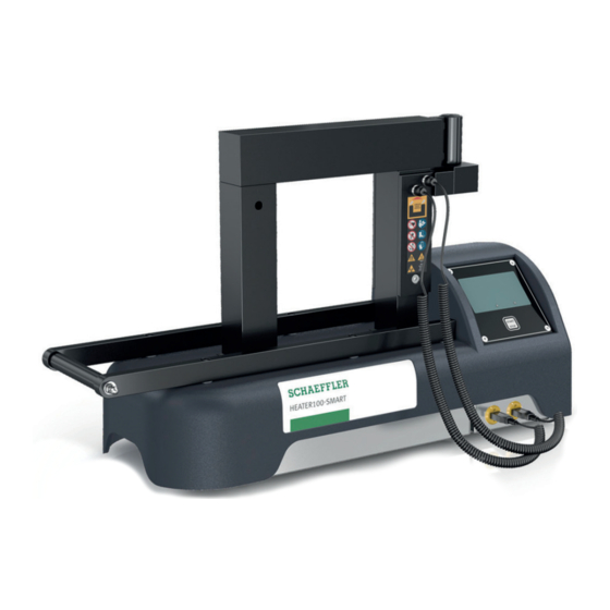
- Page 3 Foreword The induction heating devices HEATER50-SMART, HEATER100- SMART, HEATER150-SMART and HEATER200-SMART give rapid, clean operation. Their high efficiency level allows energy- efficient heating and shorter mounting times. This reduces the operating costs. The uniform, controlled heating allows consistently good quality of mounting. Operation is simple and user-friendly, the touch-sensitive screen is oil-resistant, dustproof and waterproof.
-
Page 4: Table Of Contents
English Contents 1. About the user manual ........................6 1.1 Current version .......................... 6 1.2 Availability ..........................6 1.3 Legal guidelines ........................6 1.4 Original user manual ......................... 6 2. Safety, warnings and potential hazards ..................7 2.1 Explanation of the pictograms ....................7 2.2 Description of potential hazards .................... - Page 5 10. Log functionality ........................41 10.1 Logging ..........................41 10.2 Access to the log files ......................44 10.3 Alarms ........................... 44 10.4 Last crash ..........................45 10.5 Heating logs .......................... 46 11. Other functionalities ......................... 48 11.1 Demagnetisation ........................48 11.2 Hold functionality ........................
-
Page 6: About The User Manual
1. About the user manual 1.1 Current version An induction heating unit is controlled by means of an operator unit with a touch-sensitive screen. The operator software can be developed further and an update is possible free of charge. Changes to the software can lead to adjustments in the user manual. -
Page 7: Safety, Warnings And Potential Hazards
2. Safety, warnings and potential hazards 2.1 Explanation of the pictograms Forbidden for persons with heart pacemaker or other sensitive implants. Wearing of metal parts, watches and jewellery forbidden. Forbidden for persons with metal implants. Forbidden for magnetically sensitive data media. Read the user manual! Wear heat-resistant gloves! Wear safety shoes! -
Page 8: Description Of Potential Hazards
2.2 Description of Warning! Voltage potential hazards Be aware that you are working with an electrical appliance. On the mains side as well as internally, voltages occur that can lead to serious injury and death if used inexpertly or improperly. ■... - Page 9 Furthermore, it cannot be ruled out that the electromagnetic fields could cause damage to electronic and magnetic data media. Keep such equipment away from the induction heater. Caution! Tripping hazard Limit the risk of injury due to tripping as far as possible. ■...
-
Page 10: Safety Measures To Be Taken
■ The user must carefully read this manual and be familiar 2.3 Safety measures to be taken with the safety standards in the work practice. ■ Follow the instructions in the manual at all times. ■ Check the connection voltage against the rating plate on the unit. -
Page 11: Safety Provisions
WARNING! Danger of death for persons with artificial heart valves made from metal, hazard of severe burns due to heating of implants by the electromagnetic field, see chatper 2.2. Ensure that persons with a ferromagnetic implant remain outside the hazard area of the heating device. -
Page 12: Introduction
3. Introduction 3.1 Application Schaeffler induction heaters are intended for heating bearings, so they can be assembled easily by means of a shrink fit. Subject to professional assessment, they can also be used to heat bushings, cogwheels, couplings and metal objects that form a closed circuit. -
Page 13: Installation
4. Installation ■ Remove the packaging and place the induction heater on a non-ferrous, stable and level surface. Put heaters with wheels on the brake to prevent the heaters from moving. ■ A Schaeffler heater is supplied with ledges, temperature sensor, heat-resistant gloves (suitable up to 250°C / 482°F) and acid-free lubricant. - Page 14 480V/600V 2 phase heaters Black Phase White or Zero Black Green Ground ■ Ensure that the power supply cable cannot come into contact with the workpiece to be heated. Insert the plug in a socket outlet with grounded connection. ■ Switch on the device by means of the main switch. The machine is starting up.
-
Page 15: Explanation Of Display, Buttons And Connections
5. Explanation of display, buttons and connections Touchscreen: time or temperature heating mode settings information red temperature = T1 green temperature = T2 Start /Stop button: heating / automatic demagnetisation Sensor connections T1 and T2: T1 (red on display) is the main temperature that controls the heating process. -
Page 16: Explanation Of Touchscreen Operating Elements
5.1 Explanation of The operating panel consists of a touchscreen. touchscreen operating elements Different pages are displayed on the screen with i.a. different buttons, setting possibilities and operating modes. The most frequently used buttons and how variables can be set are explained below. Start heating process. - Page 17 Reset appliance to default settings. Call up additional heating information. Adapt target heating during heating process. Access to log data. Sliders on/off. The corresponding option is switched on or off. Slider “not available”. The corresponding option cannot be switched on or off due to settings made elsewhere.
-
Page 18: System Settings
6. System settings 6.1 General The heater offers the possibility to set and adjust parameters according to personal wishes and preferences. The parameters can be set according to the demands made on a heating process. Pressing settings displays the following screen: With the buttons “page forward”... -
Page 19: Explanation Of System Settings - Screen 1
6.2 Explanation of system settings – screen 1 Default mode: Heating mode to which the heater is set and in which it starts for the first time, or to which it returns if “Default” is pressed. Default temp: Setpoint temperature at which the heater starts, or to which it returns if “Default”... -
Page 20: Explanation Of System Settings - Screen 3
6.4 Explanation of system settings – screen 3 Offset Temperature probe 1: Calibration / correction readout thermocouple 1 Offset Temperature probe 2: Calibration / correction readout thermocouple 2 Unit: Setting of the temperature measurement in °C or °F. Language: Setting of the language in which the texts on the screen are displayed. -
Page 21: Explanation Of System Settings - Screen 4
6.5 Explanation of system settings – screen 4 Min. speed alarm: Alarm if insufficient temperature increase is measured according to the Min. speed limit setting. Min. speed: Minimum temperature gradient. T hold hysteresis: Temperature at which the workpiece may be lowered before the heating process restarts automatically System info: Information about firmware versions... - Page 22 ΔT automatic restart: Activate or deactivate automatic restarting of heating as soon as ΔT is within the permitted limits of “ΔT switch on” again. ΔT switch on temperature: The temperature difference between 2 measuring points on a workpiece at which the heating process is allowed to be switched on again after previously being switched off due to exceeding of the limit value for ΔT.
-
Page 23: The Magnetic Temperature Sensor
7. The magnetic temperature sensor ■ The magnetic temperature sensor (sensor) must always be used when heating in one of the “temperature modes”. ■ The sensor can be used as a tool for temperature control whilst heating in “time mode”. ■... -
Page 24: Method Of Investigation
■ Correct sensor positions for heating with double temperature measurement and ΔT monitoring. T1 (main temperature) on the bore. T2 on the outer ring. CAREFULL! Handle the sensor with care! It is a vulnerable part of the heater. After use, place the sensor on the side of a vertical pole. - Page 25 A workpiece can be placed in 2 different ways: Hanging, with ledge through the workpiece Horizontal, with workpiece around the pole Large workpieces can be thermally insulated by wrapping them in insulating material, such as a welding blanket. This ensures that the heat stays in the workpiece and does not dissipate.
-
Page 26: Heating A Hanging Workpiece
■ Place the induction ledge with the bearing on the poles. Make 8.1 Heating a hanging workpiece sure that the ground side is positioned straight on the poles. ■ Always choose an induction ledge that fills the bore of the bearing as much as possible. -
Page 27: Heating A Horizontal Workpiece
■ This is only possible if the bore of the workpiece is large 8.2 Heating a horizontal workpiece enough to fit over the pole. ■ Place the workpiece as centrally as possible around the pole on the horizontal supports. ■ The workpiece may not be wider than the horizontal supports. -
Page 28: Operation
9. Operation There are 4 heating methods: Temperature mode ■ For controlled heating up to the desired temperature. ■ And if you want to make use of the thermostat feature. This feature maintains the heated workpiece at the pre-set temperature for a maximum period of 5 minutes. -
Page 29: Selecting Heating Modes
9.1 Selecting heating modes The various heating modes can be selected by tapping the current mode on the settings screen. A selection menu appears below the current mode, in which one of the four heating modes can be selected by tapping. The selection made is then displayed under “Mode”... - Page 30 If required, press “Default” to call up the default settings of the heater as set in the settings menu. About the heating modes Temperature mode Heating of workpieces to a set temperature; the temperature of the workpiece is monitored during the whole process. In the settings menu, it is possible to select a double measurement / ΔT measurement here.
- Page 31 Temperature and speed mode Heating of workpieces to a set temperature; the temperature of the workpiece is monitored during the whole process. In this mode, a gradient is also entered with which the heating process may take place. In the settings menu, it is possible to select a double measurement / ΔT measurement here.
-
Page 32: Heating In Temperature Mode
■ Position the workpiece and sensor (according to 9.2 Heating in temperature mode chapters 7 & 8.) ■ Switch on the heater and select the temperature mode if necessary. ■ If necessary, change the temperature set by pressing the current temperature. ■... - Page 33 By pressing the info button , the heating process is displayed graphically. Pressing info again displays additional information from the process. ■ Unless the thermostat function is switched on, heating will stop automatically when the set temperature is reached. A loud beep sounds, and the display shows information about how the heating process went.
-
Page 34: Heating In Time Mode
■ Position the workpiece and any sensors (according to 9.3 Heating in time mode chapters 7 & 8.) Only use the sensor if you want to check the temperature before the countdown has completed. ■ Switch on the heater and select the time mode if necessary. ■... -
Page 35: Heating In Temperature Or Time Mode
■ During heating, the pre-set time counts down to 00:00. When 00:00 is reached, the induction heater switches off. The workpiece is then demagnetized automatically and a loud, continuous beep sounds. Press STOP to switch off the beep. ■ Position the workpiece and sensor (according to 9.4 Heating in chapters 7 &... - Page 36 ■ If necessary, change the temperature and/or time set by pressing the current values. ■ Press ‘START’. The heating starts, you will hear a slight humming sound. ■ The display shows the temperature and the time left until process completion. By pressing the info button , the heating process is displayed graphically.
-
Page 37: Heating In Temperature & Speed Mode
■ Heating runs until the set temperature is reached or until the set time has elapsed, whichever comes first. The workpiece is then demagnetized automatically and a loud, continuous beep sounds. Press STOP to switch off the beep. ■ Position the workpiece and any sensors (according to 9.5 Heating in temperature &... - Page 38 ■ Unless the thermostat function is switched on, heating will stop automatically when the set temperature is reached. A loud beep sounds, and the display shows information about how the heating process went. The beep can be ended by pressing “stop”. ■...
-
Page 39: Workpiece Installation
■ After pressing ‘STOP’, place the sensor(s) on the side of 9.6 Workpiece installation the pole. ■ By pressing ‘STOP’, the workpiece is demagnetized automatically. ■ Wear heat-resistant gloves. Place the ledge with the workpiece on a clean surface or if the heater is equipped with a swivel arm, swivel the ledge forwards into the positioning cam, slide the workpiece off. - Page 40 “The environment temperature is The ambient temperature is higher Switch off the device and wait above 70°C” than 70°C. until the ambient temperature has dropped below 70°C (158°F). If the temperature is within the limit and the error still occurs, please contact your supplier.
-
Page 41: Log Functionality
10. Log functionality 10.1 Logging Each heating mode has a slider on the screen with which the log functionality of the heater “Log” can be activated or deactivated. This functionality offers the possibility of defining certain parameters for the heating process, such as temperature, time, power, operator and workpiece data. - Page 42 Enter the data and exit with enter. The keypad disappears from the display and the entered data is transferred to the corresponding field. Repeat the above steps, if necessary, for the other input field. Pressing “START” now starts the heating process and the heating data are coupled to the entered data, operator and project name.
- Page 43 Now the heating data can be exported to a USB data carrier as a CSV file. To do so, tap the Export button. The screen below appears as a sign that the export of the log file has been successful. Press “OK” to confirm the message and to clear the message from the screen.
-
Page 44: Access To The Log Files
10.2 Access to the log files In addition to the log functionality, which can be switched on or off, the heater automatically saves certain data from the heating process. This data includes: ■ Last crash, data from the process shortly before the generator failed (crashed) for whatever reason ■... -
Page 45: Last Crash
The type of alarm is now displayed. For example: Press “ok” to return to the previous overview screen. To leave the Alarm screen, tap “previous” 10.4 Last crash The last crash log shows – as far as possible – the heating data from shortly before the generator crashed/failed. -
Page 46: Heating Logs
10.5 Heating logs Pressing the “heating logs button” displays a list of saved heating logs. To scroll through the lines, use the arrow keys. To select a log, press the corresponding line. After selecting the desired line/file, select: View – to display the selected log file on the screen Delete –... - Page 47 Delete If you press “delete” after selecting a log file, the file may be deleted. A confirmation screen appears. If you press “no”, you return to the list of log files. If you press “yes”, a confirmation screen appears confirming that the file has been deleted.
-
Page 48: Other Functionalities
11. Other functionalities 11.1 Demagnetisation The workpiece is demagnetized each time the heating process stops or is stopped manually. This is briefly displayed on the screen. 11.2 Hold functionality In the temperature and the temperature & speed modes the screen displays a slider with which the temperature hold functionality “Temp. - Page 49 When the Hold Temp functionality is activated, the slider turns green and the hold temp duration of the workpiece is displayed. By pressing Hold Time you can adjust the hold temp duration of the workpiece. The time is entered in mm:ss and can be set between 00:01 and 99:00.
- Page 50 Once the set temperature, in this example 80°C, is reached for the first time, a timer will appear at the bottom of the screen, indicating the remaining time the workpiece is kept at the set temperature. As soon as this time has elapsed, the heater displays a message indicating that the “temp hold”...
-
Page 51: Δt Functionality
11.3 ΔT functionality This functionality is used if the temperatures in a workpiece must not differ too much in order to avoid stresses in the material. The functionality is also used for bearings when the temperatures of the inner ring and outer ring must not differ too much. - Page 52 If “Auto restart” is not active, the heating process will not restart automatically and has to be restarted manually. If “Auto restart” is active, the heating process will restart automatically as soon as the temperature difference is smaller than the temperature set under “ΔT switch on”. This must be achieved within the “ΔT timeout”...
-
Page 53: Target Functionality
11.4 Target functionality In all heating modes, a “target” button is displayed in the top right-hand corner during heating. In this example, heating in the temperature mode is used for illustration purposes. Pressing this button during heating allows the desired temperature or time (target) to be adjusted up or down without having to stop the process. -
Page 54: Cleaning, Maintenance And Troubleshooting
12. Cleaning, maintenance and troubleshooting ■ Store in a dry place, free from frost and damp. ■ Clean with a dry cloth. Never clean with water. ■ Keep the bare parts of the poles clean. Lubricate regularly with acid-free lubricant for better contact with the ledges and to prevent corrosion. - Page 55 5. When noise reduces, then tighten all bolts and switch off the heater. WARNING! Carrying out the right maintenance and following the instructions is important. Contact your supplier if in doubt about the correct functioning of the device. Repairs must be carried out by the manufacturer or a specialist approved by the manufacturer.
-
Page 56: Technical Specifications
13. Technical specifications SMART series HEATER50-SMART HEATER100-SMART HEATER150-SMART HEATER200-SMART 4.3” Touchscreen Dual Temp Frequency 50-60Hz Temperature measurement Double, ΔT measurement, Log functionality Operating modes Time, Temperature, Temperature or time, Temperature & speed Weight in kg Max. temperature 240°C / 464°F 240°C / 464°F... - Page 57 Machine ID and certification See machine plate on the machine. Available models Name Certification Voltage/Amp HEATER50-SMART-230V 230V/13A HEATER50-SMART-120V-US 120V/13A HEATER50-SMART-240V-US 240/13A HEATER100-SMART-230V 230/16A HEATER100-SMART-120V-US 120V/15A HEATER100-SMART-240V-US 240V/15A HEATER150-SMART-230V 230V/16A HEATER150-SMART-240V-US 240V/16A HEATER200-SMART-400V 2 ~ 400V/20A HEATER200-SMART-450V 2 ~ 450V/16A HEATER200-SMART-500V 2 ~ 500V/16A HEATER200-SMART-480V-US 2 ~ 480V/16A...
-
Page 58: Waste Disposal
14. Waste disposal Power tools, accessories and packaging must be reused at the end of their life cycle in an environmentally sound manner. Do not dispose of used power tools as residual waste, but bring them to a recycling company that complies with the applicable environmental requirements. -
Page 59: Certificate Of Conformity
16. Certificate of conformity CERTIFICATE OF CONFORMITY in accordance with Low Voltage Directive 2014/35/EU We hereby declare that the product described below is in conformity with the applicable health and safety requirements of the EC Directive in terms of its design and type and in the execution we have brought into circulation. - Page 60 Schaeffler Technologies...
- Page 61 Schaeffler Technologies AG & Co. KG All information has been carefully compiled and Georg-Schäfer-Straße 30 checked by us, but we cannot guarantee complete 97421 Schweinfurt accuracy. We reserve the right to make corrections. Germany Therefore, please always check whether more up-to-date or amended information is available.
Need help?
Do you have a question about the SMART Series and is the answer not in the manual?
Questions and answers