Table of Contents
Advertisement
Quick Links
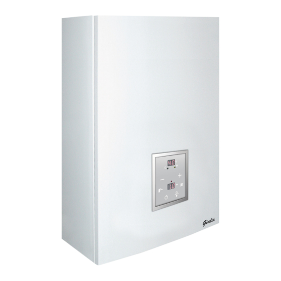
GIALIX 24 MA
COMFORT +
Wall mounted electric boiler - BC
Installation manual
• Electronic regulation
• 1 heating circuit dependent on
exterior temperature
• 1 domestic hot water circuit
Edition n
: 19.176
o
Manual ref.: 1895698
The information contained in this document is non-contractual. Auer reserves the right to modify all technical data for any equipment or appliance at any time without prior notice.
Gialix 24 MA Comfort +
Ref. 132616
Made in
France
Advertisement
Table of Contents

Summary of Contents for auer GIALIX 24 MA COMFORT +
- Page 1 • 1 domestic hot water circuit Made in France Edition n : 19.176 Manual ref.: 1895698 The information contained in this document is non-contractual. Auer reserves the right to modify all technical data for any equipment or appliance at any time without prior notice.
-
Page 2: Table Of Contents
TABLE OF CONTENTS TABLE DES MATIÈRES 3.6.8 - Lowering the boiler temperature by disconnecting the heating elements ........................20 1 - PLEASE READ IMMEDIATELY ......5 3.7 - Set-up .....................22 3.7.1 - Filling the installation ....................22 Preservation of documents ...............5 3.7.2 - Setting the regulator .....................22 1.1 - Safety ......................5 3.7.2.1 - List of parameters ..................23 Danger of death by electrocution ............5... - Page 3 GIALIX 24 MA COMFORT + -BC installer manual...
-
Page 4: Please Read Immediately
National rules and regulations 1 - PLEASE READ (directives, laws, and standards) IMMEDIATELY Once the appliance is installed and switched on, all decrees, directives, technical rules, and standards must be respected in their current version in effect Preservation of documents in the country of installation and use. -
Page 5: Introduction
Safety aquastats with manual reset Factory wired for operation on a high temperature network 2 - INTRODUCTION with 100°C high temperature limiter double male tab (black spot) 2.1 - Description (red spot) The Gialix boiler is placed inside of protective casing with a removable front panel to allow access to all parts and components of the appliance. -
Page 6: Technical Specifications
2.2 - Technical specifications 2.3 - Accessories 2.3.1 - Included Gialix 24 MA Designation Comfort + For reference numbers, please refer to the pricing guide. 400V three-phase Exterior sensor: Maximum heat output P1 24 kW (factory wired) Number of power stages 400V three-phase 50 Hz power supply P4 = 16.0 kW Adjustment of the maximum power P1*... -
Page 7: Description Of The Control Panel
2.5 - Description of the boiler 2.4 - Description of the control panel Electrical panel closed Upper 100 C Safety aquastat display 60 C Safety aquastat Winter LED Summer LED + Button Water pressure sensor 4-speed circulator Boiler operating - Button Switch to summer mode button Switch to winter... -
Page 8: Installation
3.2 - Installation recommendations 3 - INSTALLATION • Backflow prevention device French law requires that a backflow prevention device be fitted onto the installation. Please check the current laws and regulations in effect in the country of installation to ensure that 3.1 - Hydraulic schematic diagrams the installation is in compliance. -
Page 9: Treatment Of The Water In The Heating Circuit
In order for the installation to allow for continuous purging, automatic purgers must be placed at each high point of the In the case of an installation with «all installation and manual purgers must be placed on each thermostatic mixing valves», it is necessary radiator. -
Page 10: Purging The Installation
3.4 - Placement of the boiler • For new installations: (less than 6 months old): 3.4.1 - Dimensions and spacing - Hydraulic - Clean the installation with a universal cleaner to eliminate connections the debris from the installation (copper, fibres, soldering fluxes) Example: SENTINEL X300 or SENTINEL X800. -
Page 11: Placement
3.4.2 - Placement 3.4.3.2 - Wall mounting The Gialix wall mounted boiler must be placed vertically against the wall with the support of at least two 8 lag bolts. The boiler must be located at least 300mm above any obstacles to allow for the removal of the heating elements from beneath the appliance. -
Page 12: Hydraulic Connections
3.5 - Hydraulic connections 3.6 - Electrical connections Electrical connections could be accidentally loosened during transport. The heating outlet (D) and inlet (R) are To prevent risks of abnormal heating, it is connected at a high necessary to check the faston type connections point of the tank. -
Page 13: Fuse Size
Example of determination based on standard C15-100: 3.6.2 - Electrical connection terminals - Ambient temperature: 20°C - Type of cable: U1000 R02V - Length < 15 m - Installation without gaskets and with a well ventilated cable channel Placement of the cable clamp Maximum MINIMUM width per phase in mm²... -
Page 14: Connection Of Conductors Based On Voltage Supplied
3.6.3 - Connection of conductors based on voltage supplied Ground Neutral see § «Electrical connections» to determine the connection cross-section and the size of the switch with fuses or thermal magnetic circuit breaker. 3.6.4 - Control circuit schematic diagram : Phase : Neutral : Fuse A4 size 5x20 : Electronic board with display... -
Page 15: Connection To The Control Circuit
3.6.5 - Connection to the control circuit • To prevent disturbances in sensor readings by the regulator, independently wire the cables for the electrical network (raceways, cable channels), and avoid junction boxes. • The conductors must be made of electrolytic copper (no oxidization of the stripped sections of cable). -
Page 16: Wiring Diagram
3.6.7 - Wiring diagram black purple orange yellow blue white black Timer TRANSFORMER black white white black blue blue GIALIX 24 MA COMFORT + -BC installer manual... - Page 17 black purple orange yellow white black white white black blue blue : Phase AqECS : Domestic hot water aquastat AQS1 : 60°C safety aquastat with manual reset : Neutral AQS2 : 100°C safety aquastat with manual : Fuse 4A, size 5x20 SECS : Domestic hot water sensor reset...
-
Page 18: Lowering The Boiler Temperature By Disconnecting The Heating
3.6.8 - Lowering the boiler temperature by disconnecting the heating elements To supply power to the boiler using smaller fuses (see § «Setting the regulator»), it is necessary to permanently lower the boiler’s power level by disconnecting the heating elements as shown in the following diagrams: Factory wiring: 24kW L1: terminal L1 L2: terminal L2... - Page 19 Adjustment: 18.6 kW: K5-K6 • Remove the black and white power cables upstream from contactor L1: terminal L1 L2: terminal L2 L3: terminal L3 K1: contactor n˚1 K2: contactor n˚2 K3: contactor n˚3 K4: contactor n˚4 K5: contactor n˚5 K6: contactor n˚6 1- Parameter n˚17 = 01 (5.3 kW) 2- Parameter n˚18 = 01 (2.6 kW) 3- Parameter n˚19 = 01 (5.3 kW)
-
Page 20: Set-Up
3.7 - Set-up 3.7.1 - Filling the installation 3.7.2 - Setting the regulator • Fill the boiler (see § «Treatment of the heating circuit»). Function designed to be used by the • Periodically check that the installation is purging from the high installer only. -
Page 21: List Of Parameters
3.7.2.1 - List of parameters Access Parameter Factory set Definition Possible values conditions values Manufacturer Number of power stages 2; 3; 4; 5; or 6 Maximum boiler temperature (TCMA) 21 to 80 Minimum boiler temperature (TCMI) 21 to TCMA Presence of an ambient temperatute thermostat or sensor 0;... -
Page 22: Pairing Of Stages
3.7.2.2 - Pairing of stages 3.7.3.1 - Underfloor heating application To prevent the unbalancing of phases when the boiler is The boiler is delivered from the factory with a 100°C safety regulating, it is possible to pair the stages numbered 1 ;2 and 4 ; 6 aquastat;... -
Page 23: Designated Purpose Of Timer Input
3.7.4 - Designated purpose of timer input 3.7.6 - Ambient temperature readings and settings with the presence of an ambient • By setting parameter 23 = 01, the set temperature of the boiler temperature sensor is lowered by 1/8 of its value when the timer input contact is closed (terminals 20 - 21). -
Page 24: Maintenance And Troubleshooting
3.8.3 - Maintenance 3.8 - Maintenance and troubleshooting An annual maintenance check of the boiler by a qualified IMPORTANT INFORMATION professional is advised. • The pressure in the installation’s water circuit should be To avoid permanently blocking the circulator and to inspected periodically (the value shown on the pressure allow for the automatic unblocking function every 24 hours, it is IMPORTANT TO LEAVE THE BOILER SWITCHED... -
Page 25: Operating Errors
16 669 1 425 15 887 1 379 15 146 1 336 14 445 1 293 13 781 13 151 1 253 12 555 1 213 11 989 1 176 3.8.4 - Operating errors 3.8.5.2 - Boiler sensor (SC) 11 452 1 139 DHW sensor (SECS) 10 943... -
Page 26: List Of Spare Parts
3.9 - List of spare parts 4 - USE Gialix 24 MA 400V Designation Reference three- To avoid permanently blocking the circulator and phase to allow for the automatic unblocking function every 24 hours, it is IMPORTANT TO LEAVE THE BOILER Side casing B4484737 SWITCHED ON (circuit breaker engaged) during any... -
Page 27: Description Of The Control Panel
4.1.2 - Description of the control panel 4.1.3 - Operation of the electronic regulation of 2 circuits Upper display 4.1.3.1 - Turning on Winter LED Summer LED + Button The upper display screen shows which indicates that the Boiler operating - Button boiler is connected to the power supply, is turned off, and is in frost protection mode. -
Page 28: Automatic Operation
4.1.3.3.2 - Automatic operation 4.1.3.5 - How to set your heating The heating water temperature is based on the If your boiler is set for automatic operation, this function is not exterior temperature. available. To operate in automatic mode, the Gialix boiler must be Set your boiler in manual mode to adjust your heating settings. -
Page 29: How To Set The Ambient Temperature
4.1.3.7 - How to set the ambient temperature 4.1.4 - •Temperature readings •Status of connected aquastats or thermostats This setting is only possible with an ambient temperature sensor. During normal operation the boiler’s temperature is displayed on the upper display screen. •... - Page 30 6 - WARRANTY 6.1.2 - Cases (not limited to) for exclusion from warranty twenty (20) • The tank is guaranteed against breakage for a period of 6.1.2.1 - Use years three (3) years (for the cast iron heating body) and for (for the steel heating body).
- Page 31 GIALIX 24 MA COMFORT + -BC installer manual...
- Page 32 Rue de la République CS 40029 80210 Feuquières-en-Vimeu Spare parts department Tel. : 03 22 61 21 21 Fax : 03 22 61 33 35 E-mail : pieces@auer.fr Technical assistance* E-mail : sav@auer.fr *Technical assistance service is reserved for professionals.
Need help?
Do you have a question about the GIALIX 24 MA COMFORT + and is the answer not in the manual?
Questions and answers