
Subscribe to Our Youtube Channel
Summary of Contents for Rtelligent RSE Series
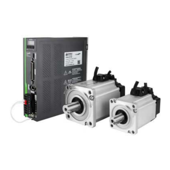
- Page 1 锐 特R S E系 列 伺 服 快 速 启 动 指 南 Rtelligent RSE series Ser vo System Quick Star t Guide Shenzhen Rtelligent Mechanical Electrical Technology Co.,Ltd...
- Page 2 Cautions Thank you for using the Rtelligent RSE series AC servo system! This operating manual provides information about the RSE series drivers and RSM series motors. Before use, please read the manual carefully to ensure proper use! Please disconnect the power supply for more than 5 minutes before removing or disassembling the driver, otherwise it may cause electric shock due to residual voltage.
- Page 3 Model combination list EtherCAT communication port (CN4, CN5) Panel operator USB debugging port (CN3) Input and output signal terminals (CN1) Power supply input Encoder interface (CN2) Braking resistor Motor interface (can be external) Grounding port Servo driver dimension drawing SizeB Below 1500W SizeA Below 400W Φ5 Φ5...
- Page 4 List of standard model combinations Motor base Model Rated power Matching driver Encoder cable Power cable RSM-M04J0130A RS100(E) SES4-030 SMS-030 RSM-M04J0330A 100W RS100(E) SES4-030 SMS-030 RSMA-M06J0630A 200W RS200(E) SES4-030 SMS-030 RS400(E) RSMA-M06J1330A 400W SES4-030 SMS-030 RSMA-M08J2430A 750W RS750(E) SMS-030 SES4-030 RSMA-M08J3230A RS1000(E) SMS-030 SES4-030...
- Page 5 Motor model description RSMA M Encoder resolution Motor rated speed RSM Series Servo Motor A:5 pole pairs,Ultra thin J: 17bit magnetic encoder 30: 3000 rpm 15: 1500 rpm none: 4 pole pairs H: 23bit optical encoder Motor inertia code G: 17bit magnetic Multi-turn absolute encoder Oil seal or not L: 23bit optical Multi-turn absolute encoder S: Small inertia A: with oil seal ...
- Page 6 CN1-DB44 control signal interface definition Functions Signal Definition Function Description differential input IN7+ 7 positive differential input IN7- 7 nagative differential input , 5V Differential differential input Emergency stop IN8+ 8 positive input differential input interface IN8- 8 nagative 24V input 7 24VIN7+ positive 24V positive 24V input 8 24VIN8+...
- Page 7 Panel operation menu Power-on initialization display Monitoring display Short press the S key Monitoring display options Press up and down keys to select, SET key to view M key Parameter setting Press up and down keys to select, SET key to view M key Long press the SET key to confirm and modify the parameters...
- Page 8 Monitor State Content Unit Content Run statement —— Speed of motor Speed command Motor torque Torque command Run current Position command counter Common unit(pulse) Encoder unit(pulse) Position feedback counter Encoder unit(pulse) Position error Pulse command speed Pulse command frequency Input signal state ——...
- Page 9 RSE driver wiring guide Single-phase 220VAC Motor cable Encoder cable 24VIN7+ IN7+ Undefined IN7- 24VIN8+ IN8+ Emergency IN8- stop Servo ready OUT1 Alarm output OUT2 24V+ OUTCOM- Output common ground INCOM Undefined Positioning complete positive DFOUT3+ Positioning completed negative DFOUT3- Probe 1 Brake positive DFOUT4+ Brake negative...
- Page 10 Brake wiring diagram 24V+ Relay BRK+ BRK- RSE SERVO DRIVER 24V- Servo motor with brake Servo driver Remarks: 1. The output signal of brake control can only be specified as OUT3 or OUT4 port, OUT4 is shown as default. 2. Motor brake cable has polarity, please pay attention to distinguish Basic parameters of position control mode...
Need help?
Do you have a question about the RSE Series and is the answer not in the manual?
Questions and answers