Table of Contents
Advertisement
Quick Links
Advertisement
Table of Contents

Related Manuals for Alamarin Jet AJ 340


Summary of Contents for Alamarin Jet AJ 340
- Page 1 Operation and maintenance manual...
-
Page 3: Table Of Contents
Table of contents Operation and maintenance manual Table of contents 1. Introduction ....................1 1.1. Safety precautions ................1 1.2. Symbols ..................... 1 2. The jet propulsion unit ................3 2.1. Structure .................... 3 2.2. Serial number ..................4 3. Operation ..................... 7 3.1. -
Page 5: Introduction
Introduction Operation and maintenance manual 1. Introduction Congratulations on purchasing your new Alamarin-Jet AJ 340 water jet propulsion unit! This manual contains important information on the operation, use and maintenance of the unit. Please read these instructions carefully before using the unit. - Page 6 Introduction Operation and maintenance manual Icon Description WARNING Negligence in the performance of the procedures can lead to personal injury, breakdown of equipment, or serious malfunction of the equipment. CAUTION The procedure involves minor danger or a possibility of minor damage to equipment.
-
Page 7: The Jet Propulsion Unit
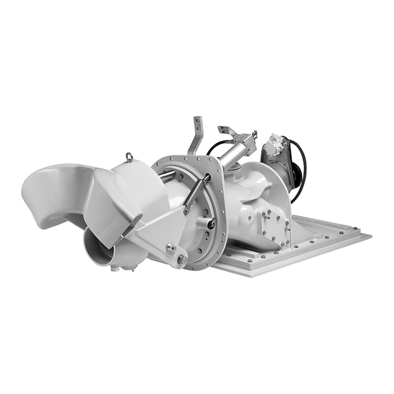
The jet propulsion unit Operation and maintenance manual 2. The jet propulsion unit The Alamarin-Jet water jet propulsion unit (jet) is a single stage mixed flow pump, which produces a high volume flow rate and thrust with high efficiency. The operation of the unit is based on increasing the water flow rate in the nozzle. -
Page 8: Serial Number
The jet propulsion unit Operation and maintenance manual Part Purpose Controlling device Causes the boat to reverse and stop. Lowering the reversing deflector causes the boat to reverse. The direction of the jet flow changes obliquely forward under the boat, which is when the thrust is directed forward and down. - Page 9 The jet propulsion unit Operation and maintenance manual Figure 3. Serial number on the body KHO/340/EN/1.0.0.
- Page 10 The jet propulsion unit Operation and maintenance manual KHO/340/EN/1.0.0.
-
Page 11: Operation
Operation Operation and maintenance manual 3. Operation If you have never driven a jet boat before, familiarise yourself with the separate guide “Steering and controlling jet boats” before driving the boat for the first time. 3.1. Starting Before you start the engine equipped with the jet, make sure that •... -
Page 12: Steering
Operation Operation and maintenance manual gap sets in place. The noise from the oil pump may be loud at first but it will disappear as the system fills up with oil. During the first few drives, the reversing deflector's hydraulic control system needs more oil than usual because the hoses and the cooler are empty. -
Page 13: Controlling
Operation Operation and maintenance manual Figure 4. Steering device Steering is possible only when the power of the jet flow is sufficient. This is why the engine must run on sufficiently high revs when steering. A suitable number of revolutions depends on the engine. Usually it is between 500 and 1,000 rpm. -
Page 14: The Settings Of The Reversing Deflector Control Lever
Operation Operation and maintenance manual Figure 5. Lowering the reversing deflector 3.3.1. The settings of the reversing deflector control lever The reversing deflector has three basic positions: forward, rear and centre. The movement of the deflector between these three positions is stepless. Forward position When the reversing deflector control lever is in the forward position, the deflector is not blocking the jet flow and the boat moves forward (figure 6). -
Page 15: Using The Reversing Deflector
Operation Operation and maintenance manual Figure 7. Astern Throttle lever Control lever Centre position The centre position of the control lever corresponds to the ”idle” position of the gearbox: even though the drive is on, the boat does not move. The centre position is not absolute as it depends on the power of the jet flow. -
Page 16: Driving Under Difficult Conditions
Operation Operation and maintenance manual the right. A good rule to remember is that the boat's bow always turns in the same direction as the wheel when reversing. When fast turns are needed, the engine revolutions are not reduced. Instead, the turn is performed through the combined motion of the nozzle and the deflector. - Page 17 Operation Operation and maintenance manual engine even out of the water, because the bearings are greased and oiled. This is a significant benefit in comparison to water-lubricated bearings, which do not sustain dry running well. The water-lubricated model should not be run dry, as this may permanently damage the propulsion unit's bearings.
- Page 18 Operation Operation and maintenance manual KHO/340/EN/1.0.0.
-
Page 19: Maintenance
Maintenance Operation and maintenance manual 4. Maintenance The jet is designed and manufactured to be as simple as possible. This is why the need for maintenance is low and maintenance can be carried out on shore. However, maintenance must be performed regularly and whenever the need arises. - Page 20 Maintenance Operation and maintenance manual The jet is protected from galvanic corrosion with passive cathodic protection, i.e. with anodes. Every critical aluminium casting has its own anode. The locations of the anodes are shown in figure 9. Figure 9. Anodes Steering nozzle (1 pc) Reversing deflector (2 pcs) Stator, outside (1 pc) Stator, inside (1 pc)
-
Page 21: Touch-Up Painting And Antifouling
Maintenance Operation and maintenance manual The stator is protected by an anode housed under a plastic plug located on the starboard side the stator. To remove the anode, first open the arrester screw and unscrew the plug. Now you can replace the anode located inside the plug. Leave the screw that holds the anode in place (figure 10, point A) loose and fasten the plug into place using a sealing compound (such as Sikaflex 221). -
Page 22: Bearing
Maintenance Operation and maintenance manual the propulsion unit can be painted with antifouling paint after installation. Generally speaking, antifouling paints are based on various soluble substances, such as copper. Because the propulsion unit is made mainly of aluminium, copper forms a highly unfavourable galvanic couple with the propulsion unit. -
Page 23: Lubricating The Front Bearing
Maintenance Operation and maintenance manual water-lubricated bushing or a grease-lubricated needle bearing, depending on the model (figure 13, point B). Figure 13. Bearing 4.3.1. Lubricating the front bearing The front bearing is oil-lubricated and the housing is secured with a mechanical sealing. When the shaft rotates, the oil circulates through the reservoir and impurities gather to the bottom of the reservoir on the drain plug magnet (figure 14, point A). -
Page 24: Lubrication Of The Rear End Bearing
Maintenance Operation and maintenance manual WARNING! Use protective gloves while handling oil. The front bearing oil must be changed after the first 20 hours of driving and then after every 500 hours or once every driving season. Before you start changing the oil, make sure you have a container for draining the used oil. -
Page 25: Control System
Maintenance Operation and maintenance manual Unlike the grease-lubricated model, the water-lubricated model cannot be run dry since the water lubricated rear end bearing requires a constant water supply in order to ensure adequate lubrication. The water-lubricated rear end bearing is an open system, and its maintenance interval depends on water quality. -
Page 26: Seals
Maintenance Operation and maintenance manual Figure 16. Reversing deflector joints 4.5. Seals The only seal that needs to be checked is the inspection hatch seal (figure 17). Figure 17. Inspection hatch seal A leaking inspection hatch seal causes ventilation or water leakage (see section 5.2. , page 37). -
Page 27: Hydraulic Reversing Deflector Control System
Maintenance Operation and maintenance manual WARNING! If an elevation collar is not used and the hatch is opened, water will flood into the engine room, quickly sinking the boat. CAUTION! If water gathers in the bilge, the cause for this must be determined immediately. - Page 28 Maintenance Operation and maintenance manual Figure 19. Cooling system The system must have the right amount of oil. If you need to add oil to the system, add it in the oil reservoir through the cap (Figure 20, point C). There is a dipstick on the reservoir cap with markings for maximum and minimum oil levels (figure 20, points A and B).
- Page 29 Maintenance Operation and maintenance manual Note that the oil must be changed once every driving season. The type of oil to use is described in appendix 3. , page 43. The system Oil recommendations can have a maximum volume of up to 1.3 L, depending on the length of the hoses.
-
Page 30: Raw Water Cooling
Maintenance Operation and maintenance manual Figure 23. Oil reservoir cover 4. Reattach the six cover screws (figure 21). 4.7. Raw water cooling The jet does not have a raw water cooling connection for the engine. 4.8. Impeller The amount of power required by the impeller depends on the pitch, length and number of blades. -
Page 31: Removing The Impeller
Maintenance Operation and maintenance manual If you suspect that there is a malfunction in the impeller, do as follows: 1. Shut down the engine and open the inspection hatch. 2. Check that there is no blockage in the intake duct. 3. - Page 32 Maintenance Operation and maintenance manual 2. Open the stator's fastening screws (figure 25). Figure 25. Stator fastening screws The stator is attached to the frame with 12 screws, all located on the same ring. The figure only shows the screws located on the port side of the frame.
- Page 33 Maintenance Operation and maintenance manual Figure 26. Removing the stator, reversing deflector and steering nozzle 4. Unscrew the screw located at the end of the shaft (figure 27, point A) and pull out the spacer (figure 27, point B) and the shaft sleeve (figure 27, point C).
-
Page 34: Installing The Impeller
Maintenance Operation and maintenance manual Shaft sleeve 5. Remove the impeller by using the extraction tool (Figure 28, point A). Slide the extraction tool on to the shaft and tighten screws through the holes on its flange to the threads on the impeller hub (figure 28, point B). Pull out the impeller by tightening the extraction screw located at the end of the extraction tool. - Page 35 Maintenance Operation and maintenance manual Figure 29. Installing the spacer plate and spacers Spacers Spacer plate Installing the impeller: 1. Place the wedge (figure 30, point A) in the wedge groove on the shaft (figure 30, point B) and push the impeller (figure 30, point C) on to the shaft.
-
Page 36: Intermediate Shaft
Maintenance Operation and maintenance manual Figure 30. Installing the wedge and the impeller Wedge Shaft's wedge groove Impeller 2. Gently push the impeller against the duct walls and use a feeler gauge to make sure that there is a gap of 0.8–1.4 mm between the impeller blade and the upper wall. - Page 37 Maintenance Operation and maintenance manual The intermediate shaft which is connected between the jet and the engine usually depends on the boat manufacturer. Contact the shaft's manufacturer for information on the maintenance of the intermediate shaft. Regardless of the manufacturer, the alignment of the intermediate shaft must be kept accurate.
- Page 38 Maintenance Operation and maintenance manual KHO/340/EN/1.0.0.
-
Page 39: Problem Situations
Problem situations Operation and maintenance manual 5. Problem situations 5.1. Cavitation The most common malfunction in water jet propulsion units manifests as cavitation. Cavitation is a phenomenon in which the water pressure decreases locally to such an extent that water vaporises on the surface of the impeller blade, creating steam bubbles. - Page 40 Problem situations Operation and maintenance manual Figure 32. Checking the grass rake for blockages 3. Check the stator or nozzle unit (figure 33). Make sure there are no extraneous objects (such as rope or reed entangled in the drive shaft, stones in the outlet port). Remove any possible blockages.
-
Page 41: Ventilation
Problem situations Operation and maintenance manual 5.2. Ventilation Ventilation produces similar symptoms and sounds like cavitation (section 5.1. , page 35), but is caused by different reasons. Cavitation Ventilation is created when air gets into the intake duct. The air causes the impeller to lose grip and the thrust weakens. - Page 42 Problem situations Operation and maintenance manual WARNING! The jet is designed to run in reverse only for one minute at a time and at under 1,500 rpm. This is usually enough to clear the blockage. Too heavy a load in reverse gear can lead to the breaking down of hydraulics.
- Page 43 Problem situations Operation and maintenance manual Figure 34. Inspection hatch 2. Locate the blockage and remove it manually. 3. Close the inspection hatch. 4. Tighten the inspection hatch nuts (4 pcs) using a wrench. WARNING! Do not open the inspection hatch when the engine is running. There is a rotating shaft behind the hatch.
- Page 44 Problem situations Operation and maintenance manual KHO/340/EN/1.0.0.
-
Page 45: Appendix 1. Declaration Of Incorporation For Partially Completed Machinery
A propulsion device transforms the torque of the motor into propulsive force. Model and type of the partially AJ 340 completed machinery: Serial number of the partially _____________________________________ completed machinery: Alamarin-Jet Oy guarantees that the abovementioned partially completed machinery meets the requirements of the Machinery Directive (2006/42/EC) and the validating national regulations. -
Page 46: Appendix 2. Grease Recommendations
Grease recommendations Operation and maintenance manual Appendix 2. Grease recommendations The grease used for lubricating the propulsion unit bearing must meet the following requirements: • lithium soap and a thickener with EP additives • mineral oil as a base oil • NLGI class 2 •... -
Page 47: Appendix 3. Oil Recommendations
Oil recommendations Operation and maintenance manual Appendix 3. Oil recommendations The operating hydraulic system of the reversing deflector and the lubrication of the front bearing are designed to use oil that is specifically intended for automatic transmission systems. The oil must meet the following requirements: Kinematic viscosity 40℃... -
Page 48: Appendix 4. Tightening Torques
Tightening torques Operation and maintenance manual Appendix 4. Tightening torques Use the tightening torques from the table 4 when tightening the propulsion unit screws. The strength grade of an acid-proof A4-80 screw is equivalent to a class 8.8 screw. Table 4. Tightening torques of the screws ... -
Page 49: Appendix 5. Test Report
Test report Operation and maintenance manual Appendix 5. Test report It is recommended that a speed test report is filled out when the boat is commissioned. The performance of the boat can later be compared to this report for the purpose of finding potential faults. The report template can be found on the following page. - Page 50 Test report, Speed © Alamarin-Jet Oy Customer: Date: Project/vessel: Test location: Air temperature: °C Seastate: Water temperature: °C Wind: m/s from Jet type: Number of units: Impeller type: Nozzle size: Engine type: Rated power: @ crankshaft [rpm] Transmission type: Reduction ratio: Load condition (total weight including all) Test 1: LCG=...
Need help?
Do you have a question about the AJ 340 and is the answer not in the manual?
Questions and answers