
Summary of Contents for Antx Messenger-W
- Page 1 Messenger-W User’s Guide Version 1.1.0 July 26, 2018 Antx 3005 Glacier Pass Lane Cedar Park, TX 78613 P: 877-686-2689 F: 512-255-8306 www.antx.com...
-
Page 2: Table Of Contents
Table of Contents Description ..........................5 Capabilities..................... 5 Monitoring ..................... 5 Host Server Communications................. 5 Installation and Setup ......................8 Installation Steps .................... 8 Unpacking the Equipment ................8 Mounting the Equipment ................8 Mounting the Antenna..................9 DIP Switch/Jumper Settings ................9 Cellular Setup .................... - Page 3 Use of the materials by the Government constitutes acknowledgment of Antx' proprietary rights in them. This manual may contain other proprietary notices and copyright information that should be observed.
- Page 4 Introduction This User’s Manual describes installation and setup of the Antx Messenger product. The Messenger is a complete monitoring, alarm notification, and telemetry platform. It supports monitoring of data values from on-board physical IO. Features The hardware feature set of this platform includes: ...
-
Page 5: Description
1 Description 1.1 Capabilities The Messenger is a highly configurable platform for remote monitoring and control applications. Some of the capabilities are listed below. local computations from monitored conditions time stamping of monitored data and events battery backed historical data/event buffers ... - Page 6 identifier to indicate the reason that a notification is being sent – e.g. normal scheduled update or an alarm detection event. A description of the protocol, format of messages, and definition of event codes is available on request. Reference protocol document “M09-PRTCLxxx”.
- Page 7 configured to be automatically set, the Messenger will set time after every power on and perform a time check every midnight. The RTC can be set in one of the following ways: Method Description This is the default setting. The Automatic Messenger will set the RTC from an via Cell...
-
Page 8: Installation And Setup
2 Installation and Setup This section provides information on installing the Messenger and confirming its initial operation. It is recommended to read the entire chapter before starting the installation. 2.1 Installation Steps Installation consists of the following steps: Unpack the Equipment. Mount the Equipment. -
Page 9: Mounting The Antenna
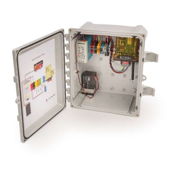
2.3.1 EEC Thermoplastic Enclosure Figure 1: Deutsch EEC Thermoplastic Enclosure Dimensions 2.4 Mounting the Antenna The antenna shipped with the Messenger is a cellular hockey puck style. The antenna can be ordered with a magnetic or a screw mount base. In general, the antenna should be mounted with an unobstructed view of the sky. -
Page 10: Cellular Setup
2.6 Cellular Setup The Messenger supports two cellular technologies, HSPA (3G) and LTE. Both of these radio options require a wireless account with a cellular provider such as AT&T, T- Mobile, Sprint, Verizon, Vodafone, etc. Table 2.4: Cellular Modem Requirements Radio Provider Account... -
Page 11: Led States
3 LED States There are 8 LEDs used to indicate various system conditions (LED locations). Specific information is conveyed to the user via LED blink patterns. Blinking of LEDs can be disabled via a configuration setting (OPTIONS Configuration). On power-up, an LED test is performed by blinking all LEDs every second for 3 seconds. - Page 12 LED 4 (RED) - CAN State Rate Definition Solid Fault, no engine bus activity detected Blink 2 blinks every OBD traffic detected, but no second response to data queries Blink 1 blink every second Engine bus not selected, check Switch 2 Solid No Faults, engine bus activity...
- Page 13 LED 8 (RED) – CELL Signal Strength (Enabled from OPTIONS Setup – default is Enabled) Rate Definition Not registered or not detectable 1 blink, 1.2 sec pause signal strength <6, weak 2 blinks, 1.2 sec pause signal strength <=12 3 blinks, 1.2 sec pause signal strength <=18 4 blinks, 1.2 sec pause...
-
Page 14: Channels
4 Channels The Messenger maps all monitored conditions into channels. Each channel has data storage and configuration parameters. Data storage holds current value, max/min values, and other run time data values. Configuration consists of user settable parameters that define rules on how the data values are to be processed (Channel Configuration). -
Page 15: Channel Data
Channel Channel Type Description Number Name 1=input voltage < 1vdc If SWX4-3 open: 1=input open 0=input voltage > 3vdc User DIN4 Digital If SWX4-4 closed: 0=input open 1=input voltage < 1vdc If SWX4-4 open: 1=input open ... - Page 16 There are a few channels that can be configured for special functions. All the physical digital input channels can accept pulse inputs (e.g. from a flow meter) and the physical analog input can be used to totalize volume when the input is flow rate. These channels have an extended data set.
-
Page 17: Sms Text Commands
5 SMS Text Commands The Messenger can receive and execute SMS commands to perform several functions. The SMS command set includes: CONFIG – used to modify configuration parameters ACTION – on-demand action request 5.1 Command Syntax The commands can be upper case, lower case, or combination. ... - Page 18 = J1939, J1708, OBD2 DATAQ d = count in queue e = deleted from queue f = failed OUTP MSGS f = failed c = count prot = protocol (Antx, Rastrac, other) modem = type of modem, jbus = type of bus...
- Page 19 SIM info text: VID(v)-MSISDN(s)-ICCID(g)-IMSI(u)-IMEI(p) data text: VID v-Running: s-52 RPM: r-x Hours: h- CoolTemp: x-Battery -OilPress - Odometer o generator control text:...
- Page 20 3005 Glacier Pass Lane Cedar Park, TX 78613 P: 512-255-2800 F: 512-255-8306 www.antx.com...
Need help?
Do you have a question about the Messenger-W and is the answer not in the manual?
Questions and answers