
Summary of Contents for Rodenstock Phoromat 2000
- Page 1 OPERATION MANUAL DIGITAL REFRACTOR Phoromat 2000 Revision 1.1 rodenstockinstruments.com Before using the instrument, be sure to read this manual thoroughly.
-
Page 2: Important Notice
© 201 3 RODENSTOCK Instrumente Am Weichselgarten 19a 91058 Erlangen / Germany All rights reserved. Under copyright laws, this manual may not be copied, in whole or in part, without the prior written consent of RODENSTOCK Instrumente. - ii -... -
Page 3: Safety Information
Phoromat 2000 Operation Manual SAFETY INFORMATION Accessory equipment connected to the analog and digital interfaces must be certificated according to the respective IEC standards (e.g. IEC 60950-1 for data processing equipment and IEC 60601-1 for medical equipment). Furthermore all configurations shall comply with the system standard EN 60601-1:2006, Clause 16. - Page 4 Phoromat 2000 Operation Manual Symbols marked on the Instrument Symbol Description Protective earth (ground) Refer to operating instructions Off (power: disconnect to the mains) On (power: connection to the mains) Disposal of your old appliance When this crossed-out wheeled bin symbol is attached to a product it means the product is covered by the European Directive 2002/96/EC.
- Page 5 Phoromat 2000 Operation Manual Only operate the instrument with the power supply indicated on the WARNING rating plate. Otherwise, it may result in fire or electric shock. Be sure to turn OFF the power switch before connecting or WARNING disconnecting the cables. Also, do not handle them with wet hands.
-
Page 6: Table Of Contents
Phoromat 2000 Operation Manual CONTENTS IMPORTANT NOTICE ---------------------------------------------------------------------- II SAFETY INFORMATION ------------------------------------------------------------------ III CONTENTS ----------------------------------------------------------------------------------- VI 1 BEFORE USE ----------------------------------------------------------------------------- 1 Outline of the Refractor -------------------------------------------------------------------------------------------------- 1 Indications for Use --------------------------------------------------------------------------------------------------------- 1 Configuration ---------------------------------------------------------------------------------------------------------------- 2 1.3.1 Refractor head ------------------------------------------------------------------------------------------------------------- 2 1.3.2... - Page 7 Phoromat 2000 Operation Manual Printing ----------------------------------------------------------------------------------------------------------------------- 34 3 ADVANCED FEATURES ------------------------------------------------------------ 35 Vision Test Screens Presented to Patient ------------------------------------------------------------------------- 36 Data List ---------------------------------------------------------------------------------------------------------------------- 38 Setting for connection with Chart projectors -------------------------------------------------------------------- 39 Setting Auxiliary Lenses ------------------------------------------------------------------------------------------------ 40 Fog Function for testing a single eye ------------------------------------------------------------------------------- 41 Fog Function for testing both eyes ---------------------------------------------------------------------------------- 42 Calling Up Data.
- Page 8 7 APPENDIX ------------------------------------------------------------------------------- 86 Linkage between Charts and Auxiliary Lenses --------------------------------------------------------------------- 86 VA Conversion Table ----------------------------------------------------------------------------------------------------- 87 Preset Addition Power --------------------------------------------------------------------------------------------------- 87 Standard Programs ------------------------------------------------------------------------------------------------------- 88 Guidance for connection of Phoromat 2000 with other devices ------------------------------------------- 90 - viii -...
-
Page 9: Before Use
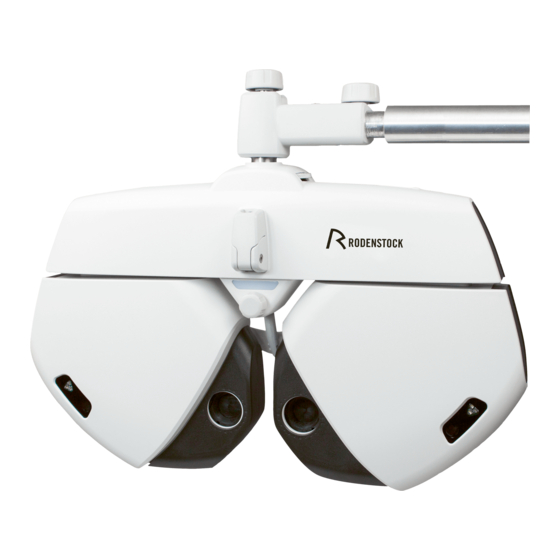
RODENSTOCK AUTO REF/KERATOMETER, LENSMETER, CHART PROJECTOR. The Phoromat 2000 includes a refractor head, control box, junction box. The control box includes the key panel and display. The display is touch-screen panel. The control box allows the data to be displayed and almost all operations to be performed. -
Page 10: Configuration
Phoromat 2000 Operation Manual 1.3 Configuration 1.3.1 Refractor head 8. Near point rod Operator’s side 7. Near point card 9. Level adjustment knob 6. Level 4. Forehead rest detection lamp 5. Forehead rest knob 2. Near point lamp 3. VD check window 1. - Page 11 Phoromat 2000 Operation Manual 1.Measuring window The patient looks at any chart through these windows. 2.Near point lamp Illuminates the near point card. The lamp lights up or goes out by pressing the ON/OFF button in ‘Near chart lamp control’ of [LAMP] pop-up on the right-up window.
-
Page 12: Control Box(Cb)
Phoromat 2000 Operation Manual The materials composed of the parts that contact the patient during refraction are as follows. NOTE - Forehead rest: polypropylene, Face shields: ABS resin 1.3.2 Control box(CB) 5. Display 3. Dial switch 3. Dial 6. Printer 2. - Page 13 Phoromat 2000 Operation Manual ○ Display ○ Control panel 11-4 11-3 11-1 11-2 13-1 14-1 14-2 13-2 12-1 12-2 - 5 -...
- Page 14 Phoromat 2000 Operation Manual 1. Data keys Used to enter the data into the Phoromat 2000 and measure each data. The selected data is displayed at the center of the screen. Which key is selected is displayed in the upper-left corner of the screen. pressing the empty data key copies the previously displayed data into that field.
- Page 15 Phoromat 2000 Operation Manual 7. Mode Keys Select the mode whose data is changed. Pressing any keys highlights the corresponding field to be changed. The value in each mode can be changed with the dial 7-1. Goes into SPH mode which allows spherical powers to be adjusted.
- Page 16 Phoromat 2000 Operation Manual 8. Eye selection keys Select the right eye (R), left eye (L), or both eyes (BIN) for subjective refinement. - The occluder is placed automatically in the non-selected eye side. , it is not placed during the binocular vision test with polarizing.
- Page 17 Phoromat 2000 Operation Manual 11-4. Isolates a horizontal line in the middle of the VA chart. : Applies the red-green filter on the VA chart. again : Releases the red-green filter. 12. Program keys See “2.5 Standard Program Refraction” (Page 25) for programmed refraction.
- Page 18 Phoromat 2000 Operation Manual ○ Bottom of the control box 1. CMOS BATTERY COVER 1. CMOS BATTERY COVER Used for changing CMOS BATTERY. - 10 -...
-
Page 19: Junction Box (Jb)
Phoromat 2000 Operation Manual 1.3.3 Junction box (JB) This junction box is installed in the system table normally. AR Connector LM Connector AUX Connector PC Connector CP Connector Power switch Power inlet Fuse holder CB Connector RH Connector 1. RK connector Connects to an auto Ref/Keratometer. -
Page 20: Labels
Phoromat 2000 Operation Manual 1.4 Labels The symbols shown on the display correspond to the symbols and those names defined in ISO 10341(Ophthalmic instruments - Refractor heads) as shown in the following table. Marking Auxiliary lens Phoromat 2000 ISO 10341... -
Page 21: Before First Use
Phoromat 2000 Operation Manual 1.5 Before First Use 1. Confirm that the power cord of the Phoromat 2000 is connected into the wall outlet. Connect ‘Refractor head’ to Junction box’ with communication cable(RH-JB). Connect ‘Control box’ to Junction box’ with communication cable(CB-JB). -
Page 22: Getting Started And Exiting
1.6.2 Restore from power saving mode The Phoromat 2000 is not operated for about 15 minutes (variable) without any key operation, it goes into power saving mode. In this mode, the screen backlight and chart presenting device lamp go out. -
Page 23: Operating Procedures
Phoromat 2000 Operation Manual 2 OPERATING PROCEDURES 2.1 Operation Flow 1.6.1 Getting started (page 14) 2.2 Entering Data (page 16) 2.2.1 From an auto Ref/Keratometer ........ -
Page 24: Entering Data
Ref/Keratometer, the measured data will be automatically transferred to the Phoromat 2000 by pressing the Print button of the auto Ref/Keratometer. The Phoromat 2000 stores the data in the DOM DISK of the control box(CB). When the data is already in the memory, skip Steps 1 and 2. -
Page 25: From A Lensmeter
Phoromat 2000 by pressing the Print button of the lensmeter. The Phoromat 2000 stores the data in the memory of the relay box. When the data is already in the memory, skip Steps 1 and 2. -
Page 26: From A
Phoromat 2000 Operation Manual 2.2.3 From a PC 1. Push the ‘Menu’ button in the CB(Control Box). 2. Push the ‘PARASET’ button on the screen. 3. Push the ‘6’ tab button on the screen. 4. Change the properties info. of the ‘Import data from PC’... - Page 27 Phoromat 2000 Operation Manual 5. You can see the changed properties of ‘Import data from PC’ as ‘Yes’. 6. Push the ‘SAVE’ button. 7. Push the ‘Clear’ button in the CB(Control Box). 8. Initialize the status of PDR-7000 as pushing the ‘OK’...
- Page 28 Phoromat 2000 Operation Manual 9. Transfer the data from PC to PDR-7000. CAUTION Please wait until finishing the transmission for safety data transmission. 10. Push the ‘IN’ button and ‘PC’ button in order and you can see the NO info. of imported data.
-
Page 29: Manual Data Entry With The Dial
Phoromat 2000 Operation Manual 2.2.4 Manual data entry with the dial Manual data entry is also available with the dial. When the AR or LM data is entered with the dial, the subjective data field does not open automatically. The subjective refinement starts with the data when is pressed. -
Page 30: Setting Prism
Phoromat 2000 Operation Manual 2.3 Setting Prism 2.3.1 Switching between rectangular and polar coordinates Press [XY] or [rθ] on the screen. This key toggles between rectangular (XY) and polar coordinates (rθ). Example) Right eye: 1.0ΔBI, 1.0ΔBU 1.40Δ, BASE 45° Left eye: 2.0ΔBO, 1.5ΔBD 2.50Δ, BASE 323°... -
Page 31: Polar Coordinates
Phoromat 2000 Operation Manual 2.3.3 Polar coordinates (rθ) 1. Press The rotary prism lenses are placed in the refractor head. The prism powers are highlighted in the central screen. 2. Enter the prism absolute values. Turn the dial to change the absolute values (in increments of 0.5Δ). -
Page 32: Preparation
Phoromat 2000 Operation Manual 2.4 Preparation 1. Place the refractor head in front of the patient’s eyes. Clean the forehead rest, face shields, and measuring windows beforehand. See “5 MAINTENANCE”. Instruct the patient to lean against the forehead rest and look through the measuring windows. -
Page 33: Standard Program Refraction
Phoromat 2000 Operation Manual 2.5 Standard Program Refraction The Phoromat 2000 includes two standard programs (Fixed Programs 1/2) for full- corrected far value and prescription. See “7.4 Standard Programs” for all test items in the standard programs. 2.5.1 Fixed Program 1 1. - Page 34 Phoromat 2000 Operation Manual 7. Enter the LM data 1) Measure the patient’s glasses with a lensmeter and print the result. 2) Press . Confirm that the data No. is the same as the print data No. of the lensmeter.
- Page 35 Phoromat 2000 Operation Manual In this spherical refinement, circle of least confusion is maintained on the retina for NOTE the next cylindrical axis measurement with the cross cylinder. When the patient can not see the red and green sides equally, make the green side sharper slightly.
- Page 36 Phoromat 2000 Operation Manual 13. Refine the spherical power with the red- green chart. 1) Press The SPH +0.50 D lens is automatically added to fog the vision. The red-green chart is presented. 2) Reduce fogging gradually until sharpness of the letters on the red and green sides appears equal.
- Page 37 Phoromat 2000 Operation Manual 17. Perform the binocular balance test. 1) Press The polarizing filters are placed in the measuring windows. Right eye: 135°, Left eye: 45° 2) Make the top and bottom lines appear equal. The top line is sharper.
- Page 38 Phoromat 2000 Operation Manual 19. Perform adjustment. 1) Press 2) Check patient’s flexibility corrective lenses. When making a decision about the patient’s flexibility based on age, the dividing line is about 40 years of age. The far powers are adjusted automatically and set in [Final 1].
- Page 39 Phoromat 2000 Operation Manual 25. Check the near visual acuity. 1) Press The cross cylinder lenses are removed. Set the values of the addition powers adjusted in Step 19 substructed from the ones measured in Step 24 as the addition powers for prescription.
-
Page 40: Chart Presentation
Phoromat 2000 Operation Manual 2.6 Chart Presentation 2.6.1 Chart selection Pressing a desired chart button at the right of the screen presents the corres- ponding chart. The selected chart is displayed at the center of the screen. 2.6.2 Visual acuity chart mask functions Press any mask key on the control box to use the mask functions. - Page 41 Phoromat 2000 Operation Manual ○ How to isolate a single letter Press The letter in the upper-right corner of the chart is isolated. Press The letter in the upper-left corner of the chart is isolated. The letter in the lower-left corner of the chart is isolated.
-
Page 42: Printing
Phoromat 2000 Operation Manual 2.7 Printing The data is printed with The contents of the printout can be selected with the Print format parameter. See “3.12 Parameter Settings” ○ Whether the data is cleared after printing The Clear after print parameter selects whether the displayed data is cleared automatically after printing. -
Page 43: Advanced Features
Phoromat 2000 Operation Manual 3 ADVANCED FEATURES This section explains the more useful features of the Phoromat 2000. ● To show vision test screens to the patient ⇒ 3.1 Vision Test Screens Presented to Patient ● To list measured data ⇒... -
Page 44: Vision Test Screens Presented To Patient
Phoromat 2000 Operation Manual 3.1 Vision Test Screens Presented to Patient Phoromat 2000’s display provides Touch-Screen Function with broad 10.4” display Phoromat 2000 provides TILT and SWIVEL Functions Instead of the normal measurement screen, it is possible to show images like near vision chart, schematic section of eye, refraction status patterns, ideal visions. - Page 45 Phoromat 2000 Operation Manual - 37 -...
-
Page 46: Data List
Press 2) Press [Data List] 2. Select a desired data. Select the data with the function button. [F/N] switches between the far and near modes. [Trans to PC] sends Phoromat 2000 measured data to PC [Others] displays other measurement results. -
Page 47: Setting For Connection With Chart Projectors
Phoromat 2000 Operation Manual 3.3 Setting for connection with Chart projectors 1. Turn on the power of the Phoromat 2000 2. Press the ‘MENU’ key button of the Control Box. 3. Select ‘Select Chart’ button. 4. Select the type of chart you want to connect with Phoromat 2000. -
Page 48: Setting Auxiliary Lenses
Phoromat 2000 Operation Manual 3.4 Setting Auxiliary Lenses Auxiliary lenses are automatically placed according to a selected chart. However, setting other lenses are also possible as follows: * It is possible to switch the lens power for retinoscope (+1.5/+2.0) and to set the fog amount for both eyes open. -
Page 49: Fog Function For Testing A Single Eye
Phoromat 2000 Operation Manual Increases or decreases the fog amount Δ Base up prism of 6 Δ Base in prism of 10 Δ Δ Base down prism of 3 in the right eye, base up prism of 3 in the left eye. -
Page 50: Fog Function For Testing Both Eyes
Phoromat 2000 Operation Manual 3.6 Fog Function for testing both eyes It is possible to test both eyes while the both measuring windows are opened. 1. Change the setting about the ‘Fog’. 1.1. Click the ‘Menu’ button on the CB. -
Page 51: Calling Up Data
This function prevents auxiliary lenses or mode (S/C/A) from being switched automatically when changing a chart. See “3.11 Parameter Settings”(page 49). 3.9 Programming The Phoromat 2000 has ten programs of Fixed(1,2) and User(1~8). The standard program has already been written in Fixed Programs A and B as factory setting. -
Page 52: Programming
Phoromat 2000 Operation Manual 3.9.1 Programming To program Fixed Program 1 or 2, set these programs to User beforehand. 1. Display the Programming screen. Call up the Main Menu screen. Press Press [Programming]. [Select] : Selecting preset program [Edit] : Editing the selected program 2. -
Page 53: Operating Programs
Phoromat 2000 Operation Manual • Cross cylinder test • Fog amount • Data to be entered (Unaided to Final) • Auxiliary lenses • With or without beep sounds • Whether the near point lamp lights up or goes out - It is impossible to select the cross cylinder setting between Flipped and Auto. Set the lens type with the Cross cylinder (XC) test parameter. -
Page 54: Entering Comments
Phoromat 2000 Operation Manual 3.10 Entering Comments It is possible to print comments such as shop name together with the measured data. Up to 24 characters can be entered in a line. Two lines are available for a total of 48 characters. -
Page 55: Setting Time And Date
Phoromat 2000 Operation Manual 3.11 Setting Time and Date The clock in the Phoromat 2000 can be adjusted. 1. Display the Adjust Clock screen. Call up the Main Menu screen. Press Press [Time set]. 2. Press the item to be adjusted. -
Page 56: Touch-Screen Panel Calibration
Phoromat 2000 Operation Manual 3.12 Touch-screen Panel Calibration The touch-screen panel is calibrated. When incorrect responses from the touch-screen panel are received, the detection point of the touch screen panel may shift from the pressure point of the touch- screen pen. In this case, calibrate the touch screen panel. -
Page 57: Parameter Settings
Phoromat 2000 Operation Manual 3.13 Parameter Settings 1. Display the parameter setting screen. Call up the Main Menu screen. Press Press [Paraset]. 2. The pages can be changed by pressing [1] ~ [7] Tab in the upper side of the window. - Page 58 Phoromat 2000 Operation Manual SPH step (Shift): 1.00 D, 2.00 D, 3.00 D Factory setting: 1.00 D Setting of the increment to adjust sphere values with . Selectable among 1.00 D, 2.00 D, and 3.00 D. CYL step (Shift): 1.00 D, 2.00 D, 3.00 D Factory setting: 1.00 D...
- Page 59 Phoromat 2000 Operation Manual 12. Preset ADD: Yes, No Factory setting: Yes Selection of whether or not to enter the patient’s age and preset the estimated additional power when is pressed. The estimated additional power is lower than the actual one corresponding to the age.
- Page 60 Phoromat 2000 Operation Manual 21. Print list: Yes, No Factory setting: Yes When the setting is Yes, the data list is displayed automatically when is pressed. Confirm that all necessary tests have been performed and press again to print the data.
- Page 61 Setting of near lamp link. 29. Chart link: Yes, No Factory setting: Yes Selection of whether or not to use the chart presenting device other than RODENSTOCK. Select No to use the chart presenting device other than RODENSTOCK. 30. Link off(Lens): Yes, No...
-
Page 62: Clearing Stored Data
Phoromat 2000 Operation Manual 39. Paraset Initialization : Execution Initializing the parameter value as the Factory setting. Press the [OK] button of confirmation window after clicking the [Execution]. *Now 7 page is empty. so it does not be selected. -
Page 63: Test Method
Phoromat 2000 Operation Manual 4 TEST METHOD 4.1 Unaided Visual Acuity Test 1. Press 2. Press The left measuring window is occluded. 3. Obtain the unaided VA for the right eye. Change the chart with The VA of the last presented chart is in the VA field. -
Page 64: Astigmatism Test
2. Present the astigmatism clock dial chart. Press The Phoromat 2000 goes into CYL mode. When the cylinder value is not 0, change it to 0. 3. Fog the vision until the VA becomes about 20/200. -
Page 65: Astigmatism Test With Cross Cylinder Lens
See “4.4.1 Red-green test” 3. Present the dots chart. Press The Phoromat 2000 goes into AXIS mode. The cross cylinder lens is set. 4. Measure the cylindrical axis. See “2.5.1 Fixed program 1” 5. Go into CYL mode. -
Page 66: Spherical Refinement
2. Present the red-green chart. Press the red-green chart The Phoromat 2000 goes into SPH mode. 3. Fog the vision. Turn the dial counterclockwise by increments of two to add SPH + 0.50 D. -
Page 67: Cross Grid Test For Far Vision
Phoromat 2000 Operation Manual 4.4.2 Cross grid test for far vision Use: Spherical refinement Chart: Cross-grid Auxiliary lens: ±0.50 D cross cylinder lens (Fixed with the axis set at 90º.) Ideal appearance: The sharpness of the horizontal and vertical lines appears equal. -
Page 68: Binocular Visual Function Test
[Procedure example] 1. Present the binocular balance chart. Press the binocular balance testing chart The polarizing filters are placed in the measuring windows. The Phoromat 2000 goes into SPH mode. 2. Fog the binocular vision. Press and turn the dial counterclockwise so that the binocular VA becomes between 20/30 and 20/25. -
Page 69: Polarized Red-Green Test
1. Present the polarized red-green chart. Press the polarized red-green chart. The polarizing filters are placed in the measuring windows. The Phoromat 2000 goes into SPH mode. 2. Ask the patient, “How do the four numbers and double circles appear?”. -
Page 70: Phoria Test
Phoromat 2000 Operation Manual 4.5.3 Phoria test Use: To detect exophoria, esophoria, hypophoria, and hyperphoria Chart: Phoria Auxiliary lens: Right eye 135°, left eye 45°, polarizing filters, binocular rotary prism Ideal appearance (Rodachart 420) Right eye Left eye Binocular ideal... - Page 71 Phoromat 2000 Operation Manual Appearance of chart Phoria Correction Turn the dial clockwise to add the BO prism Esophoria powers until a cross is formed. Turn the dial counterclockwise to add the BI Exophoria prism powers until a cross is formed.
-
Page 72: Phoria With Fixation Test
Phoromat 2000 Operation Manual 4.5.4 Phoria with fixation test Use: To detect heterophoria by giving stimuli for fusion Applicable model: Rodachart 420 Auxiliary lens: Right eye 135°, left eye 45°, polarizing filters, binocular rotary prism Ideal appearance: Right eye Left eye... - Page 73 Phoromat 2000 Operation Manual When a cross is not formed, correct it as follows: Phoria Appearance of chart Correction Turn the dial clockwise to add the BO prism Esophoria powers until a cross is formed. Turn the dial counterclockwise to add the BI Exophoria prism powers until a cross is formed.
-
Page 74: Von Graefe Test (Horizontal Phoria)
Phoromat 2000 Operation Manual 4.5.5 Von Graefe test (horizontal phoria) Use: To detect horizontal phoria Chart: Vertical line Applicable model: Rodachart 420 [For the other types, use the highest VA letter chart or the letter chart which is little higher than the patient’s VA.] Auxiliary lens: 6ΔBU to the right eye, rotary prism to the left eye... -
Page 75: Von Graefe Test (Vertical Phoria)
Phoromat 2000 Operation Manual 4.5.6 Von Graefe test (vertical phoria) Use: To detect vertical phoria Chart: Horizontal line Applicable model: Rodachart 420 [For the other types, use the highest VA letter chart or the letter chart which is little higher than the patient’s VA.] Auxiliary lens: Rotary prism to the right eye, 10ΔBI to the left eye... -
Page 76: Vertical Coincidence Test
Phoromat 2000 Operation Manual 4.5.7 Vertical coincidence test Use: To detect aniseikonia and to correct vertical phoria Chart: Vertical coincidence Applicable model: Rodachart 420 Auxiliary lens: Right eye 135°, left eye 45°, polarizing filters, binocular rotary prism Ideal appearance: Right eye... - Page 77 Phoromat 2000 Operation Manual When they are not aligned, correct them as follows: Appearance of chart Phoria Correction Press . Turn the dial counterclockwise Right eye until the left and right frames are aligned. hyperphoria (Add BD to the right eye and BU to the left eye.)
-
Page 78: Horizontal Coincidence Test
Phoromat 2000 Operation Manual 4.5.8 Horizontal coincidence test Use: To detect aniseikonia and to correct horizontal phoria Chart: Horizontal coincidence Rodachart 420 Applicable model: Auxiliary lens: Right eye 135°, left eye 45°, polarizing filters, bino cular rotary prism Ideal appearance:... - Page 79 Phoromat 2000 Operation Manual When they are not aligned, correct them as follows: Appearance of chart Phoria Correction 1) The top frame is shifted to the left. Press . Turn the dial counterclockwise until Right eye the top and bottom frames are aligned.
-
Page 80: Schober Test
Phoromat 2000 Operation Manual 4.5.9 Schober test Use: To correct heterophoria Chart: Schober Applicable model: Rodachart 420 Auxiliary lens: Red filter on the right eye, green filter on the left eye, binocular rotary prism Ideal appearance: Right eye Left eye... - Page 81 Phoromat 2000 Operation Manual When the cross is shifted from the center, correct it as follows: Phoria Correction Appearance of chart Turn the dial clockwise to add the BO prism Esophoria powers until the cross comes to the center of the circle.
-
Page 82: Stereo Test
Phoromat 2000 Operation Manual 4.5.10 Stereo test Use: To detect stereoscopic vision Chart: Stereo test Applicable model: Rodachart 420 Auxiliary lens: Right eye 135°, left eye 45°, polarizing filters Ideal appearance: Right eye Left eye Binocular ideal 1. Present the stereo test chart. -
Page 83: Worth Test
Phoromat 2000 Operation Manual 4.5.11 Worth test Use: To detect fusion and suppression Chart: Worth Auxiliary lens: Red filter on the right eye and green filter on the left eye Ideal appearance: Right eye Left eye Binocular ideal Green Green Pink or Red/Green 1. -
Page 84: Maddox Test (Horizontal Phoria)
Phoromat 2000 Operation Manual 4.5.12 Maddox test (horizontal phoria) Use: To detect horizontal phoria Chart: Fixation Auxiliary lens: Horizontal maddox rod to the right eye, rotary prism to the left eye Ideal appearance: Right eye Left eye Binocular ideal 1. Present the fixation chart. -
Page 85: Maddox Test (Vertical Phoria)
Phoromat 2000 Operation Manual 4.5.13 Maddox test (vertical phoria) Use: To detect vertical phoria Chart: Fixation Auxiliary lens: Rotary prism to the right eye, vertical maddox rod to the left eye Ideal appearance: Right eye Left eye Binocular ideal 1. Present the fixation chart. -
Page 86: Maintenance
Phoromat 2000 Operation Manual 5 MAINTENANCE 5.1 Troubleshooting In the event that the Phoromat 2000 does not work correctly, check the problem according to the following table before contacting your authorized distributor. Symptom Action • Confirm that the power cord is connected to a wall outlet. - Page 87 Phoromat 2000 Operation Manual C. Connect the connecting cable between JB and CB and turn on the power of JB like right picture. D. Click the reset switch marked with the red circle once after that the contents are displayed on the screen of CB if the reset is processed normally.
-
Page 88: Replacing Fuses
When the Phoromat 2000 does not normally turn on, the fuses may be blown. Replace them with the spare fuses provided. When the Phoromat 2000 is connected to the system table, the junction box is in the system table. Replace the fuses of the system table according to the system table operator’s manual. -
Page 89: Replacing Printing Paper
Remove the face shields before removing the patient’s side protective glasses. Attach the protective glasses with the screws just after cleaning. Failure to do so could allow dusts to be settled inside the Phoromat 2000. It may affect the NOTE viewability or cause malfunction. -
Page 90: Cleaning Exterior
It may ruin the surface of the refractor. 5.7 Service Information If you can’t contact with your local distributor, you can directly get in touch with the service department of the RODENSTOCK using the phone number and the address written in the below table. Distributor:... -
Page 91: Technical Informations
Phoromat 2000 Operation Manual 6 TECHNICAL INFORMATIONS 6.1 Classifications Classification under the provision of 93/42/EEC (MDD): Class I Type of protection against electric shock: Class I Degree of protection against ingress of water in accordance with IEC60529: IP20 Method of sterilization or disinfection recommended by the manufacturer: Not... -
Page 92: Specifications
Phoromat 2000 Operation Manual 6.3 Components Refractor head Control box Junction box Vision chart assembly Position bar Communication cable (JB - RH) Communication cable (JB - CB) Communication cable (JB - RK) Communication cable (JB - CP) Power cord Dust cover... -
Page 93: Appendix
Phoromat 2000 Operation Manual 7 APPENDIX 7.1 Linkage between Charts and Auxiliary Lenses The following table shows the auxiliary lenses linked to the charts when the Chart link parameter is set to Yes. Auxiliary lens Chart MODE Right eye Left eye... -
Page 94: Va Conversion Table
Phoromat 2000 Operation Manual 7.2 VA Conversion Table Decimal Fraction(feet) Fraction(meters) 0.05 20/400 6/120 20/200 6/60 0.15 20/150 6/45 20/100 6/30 0.25 20/80 6/24 20/70 6/21 0.32 20/60 6/18 20/50 6/15 20/40 6/12 0.63 20/30 20/25 6/7.5 20/20 20/15 6/4.5 20/20 7.3 Preset Addition Power... -
Page 95: Preset Addition Power
Phoromat 2000 Operation Manual 7.4 Standard Programs The Phoromat 2000 has ten programs of Fixed Program(1,2) and User Program(1-8), which can be programmed by the user. The following standard programs have already been written in (Fixed)Programs 1 and 2 as factory setting. - Page 96 Phoromat 2000 Operation Manual ○ Fixed Program 2 The unaided and aided VA tests and auto adjustment are omitted from Fixed Program 1. It is necessary to enter the objective and subljective (copied from the objective) data with an auto refractometer before Fixed Program 2.
-
Page 97: Guidance For Connection Of Phoromat 2000 With Other Devices
Phoromat 2000 Operation Manual 7.5 Guidance for connection of Phoromat 2000 with other devices 1. Connect all cables as the below configuration - Before connecting cables, be sure to TURN OFF the power switch of all devices. - If it is NOT TURNED OFF while connecting cables, it may cause the damage to electronic parts. - Page 98 Phoromat 2000 Operation Manual Connectors Junction Conectors Devices Refractor Head Communication cable (JB - RH) : 5m Control Box Communication cable (JB - CB) : 3m Auto ref- keratometer Communication cable (JB - PRK) : DIN 6-pin to RS-232 (5m)
- Page 117 Baca buku panduan ini dengan seksama sebelum menggunakan alat ini untuk memastikan operasi yang benar dan aman. Jika Anda memiliki pertanyaan tentang pengoperasian, silahkan hubungi Rodenstock atau distributor lokal kami. Selalu mengikuti prosedur operasi yang dijelaskan dalam manual ini. Simpan panduan ini di lokasi yang siap tersedia saat mengoperasikan instrumen Hubungi distributor lokal anda jika Anda kehilangan manual ini.
- Page 118 SIMBOL YANG DIGUNAKAN DALAM MANUAL OPERATOR INI Simbol yang digunakan dalam manual ini mewakili arti sebagai berikut. Berisiko sangat tinggi dari cedera serius atau kematian kecuali instruksi diperhatikan. Kemungkinan cedera serius atau kematian kecuali instruksi diperhatikan. Kemungkinan cedera kecil, cacat menengah atau kerugian...
- Page 119 DAFTAR ISI SEBELUM MENGGUNAKAN 1.1 Tindakan pencegahan keselamatan 1.2 Membongkar 1.3 Kosa Kata 1.4 Gambarah Operasi NAMA DAN FUNGSI KOMPONEN 2.1 Sisi Dokter 2.2 Side Pasien 2.3 Layar Pengukuran 2.4 Prosedur Operasi dari Joystick 2.5 Keselarasan Sentuhan 2.6 Konektor RS-232C PROSEDUR OPERASI 3.1 Instalasi 3.1.1...
- Page 120 3.1.3 Menghubungkan Kabel Listrik 3.1.4 Pemeriksaan kertas printer 3.2 PERSIAPAN UNTUK PENGUKURAN 3.2.1 Memulai operasi instrumen 3.2.2 Memilih mode pengukuran dan pengaturan kondisi pengukuran 3.2.3 Menyesuaikan posisi Pasien 3.2.4 Prosedur Penyelarasan 3.3 PENGUKURAN 3.3.1 Mode pengukuran daya refraktif 3.3.2 modus pengukuran kelengkungan kornea...
- Page 121 3.5 PRINTOUT 3.5.1 Prosedur Printing-out 3.5.2 Modus Print 3.6 TAMPILAN DATA MEMORI 3.7 MANAJEMEN DATA DENGAN "DATA LINK" 3.7.1 Pengaturan...
- Page 122 NAMA DAN FUNGSI KOMPONEN 2.1 SISI DOKTER KEPALA PENGUKURAN Bagian dimana pengukuran dilakukan. MONITOR / PANEL SENTUH Layar pengukuran berbagai pengaturan layar ditampilkan. Berbagai pengaturan operasi juga dilakukan dengan menekan tombol panel sentuh yang disediakan dalam monitor kristal cair. (Lihat Bagian 2.5.) JOYSTICK Kepala Pengukuran disesuaikan atas / bawah / kiri / kanan dengan Joystick tersebut.
- Page 123 TOMBOL JOYSTICK Pengukuran dimulai dengan tombol ini ATAS / BAWAH MENYESUAIKAN CINCIN Kepala Pengukuran yang keras disesuaikan atas dan ke bawah dari cincin. Sedikit disesuaikan dengan memutar Cincin. (Lihat Bagian 2.4.) HAND REST Hand Rest digunakan untuk menempatkan tangan ketika sedang digunakan untuk mengubah Joystick tersebut.
- Page 124 10) TOMBOL MEMILIH MODE LAYANAN Tenaga pelayanan kami menggunakan tombol ini untuk pemeliharaan. Jangan mengubah pengaturannya. 11) TOMBOL CLEAR Data pengukuran dihapus dengan tombol ini. 12) TOMBOL MODE Modus pengukuran dipilih. 13) TOMBOL PRINT Mulai pencetakan 14) TOMBOL OTOMATIS Perubahan atas Pengukuran Otomatis atau Pengukuran Manual.
- Page 125 18) TOMBOL CHIN REST Chin Rest naik dengan menekan tombol "A" dan turun dengan menekan tombol "V", 19) LAMPU DAYA Lampu Daya menyala sementara Daya menyala. 2.2 SIDE PASIEN JENDELA PENGUKURAN Pasien melihat pada target fiksasi melalui Jendela Pengukuran...
- Page 126 CHIN REST Chin pasien ditempatkan pada Chin Rest HEAD REST Forehead pasien ditempatkan pada Head Rest. TOMBOL POWER Daya dihidupkan dengan menekan sisi "I" (ON)" dan dimatikan dengan menekan sisi "O (OFF)". KONEKTOR DAYA Kabel listrik dihubungkan ke kabel daya. PEGANGAN SEKERING Sekering ditempatkan di Pegangan Sekering TARGET FIKSASI...
- Page 127 2.3 LAYAR PENGUKURAN TAMPILAN MODUS PENGUKURAN "RK" / "REF" / "KRT" / "DIA" / "CL" Mode pengukuran (Ref-keratometer "RK" / Refractometer "REF" / Keratometer "KRT" / diameter pupil diameter kornea "DIA" / Hubungi kurva dasar lensa "CL" akan ditampilkan.
- Page 128 TOMBOL TAMPILAN MATA PEMERIKSAAN "R" / "L" Sisi mata Kanan atau Kiri yang diperiksa ditampilkan dalam warna. Jika menekan tombol ketika mengubah ke mata pemeriksaan sisi lain, sebagian besar menggerakkan Kepala Pengukuran. NOMOR IDENTIFIKASI "No." Nomor mengidentifikasi ditampilkan. "1" ditambahkan ke nomor identifikasi sebelumnya untuk pengukuran.
- Page 129 TOMBOL SETUP Kondisi operasi masing-masing fungsi ditetapkan dengan tombol ini. TOMBOL MODUS Modus pengukuran dipilih dengan tombol ini. Tombol Sementara Tombol ini digunakan untuk mengatur sementara kondisi pengukuran untuk pemeriksaan tunggal. TOMBOL DATA Data yang disimpan dalam memori akan ditampilkan. 10) TAMPILAN CHIN REST, TINGGI Tinggi dari Chin Rest saat ini ditampilkan dalam tujuh level.
- Page 130 13) DATA PENGUKURAN KERATOMETER Data pengukuran keratometer terbaru akan ditampilkan. K1: meridian utama lemah K2: Meridian utama kuat AX: sudut aksial astigmantis kornea 14) TAMPILAN NOMOR DATA MEMORI Menampilkan jumlah memori data dengan tiga prioritas kelonggaran warna dalam urutan "Hijau" "Kuning"...
- Page 131 18) CINCIN TARGET Indikator posisi mata untuk diperiksa saat pengukuran. 19) CINCIN DIAMETER PUPIL MINIMUM Diameter pupil minimum terukur ditunjukkan. 20) CINCIN KESELARASAN OTOMATIS Rentang efektif keselarasan otomatis ditampilkan. 21) INDIKATOR FOKUS Jarak antara Kepala Pengukuran dan mata untuk diperiksa ditunjukkan.
- Page 132 25) TOMBOL BACKUP KEPALA Backup kepala ke arah operator. 26) TAMPILAN ASTIMATIS TIDAK BERATURAN KORNEA Hasil pengukuran astigmatis tidak teratur kornea. 2.4 PROSEDUR OPERASI DARI JOYSTICK Dua cara operasi Joystick, satu adalah untuk penyesuaian kasar dan yang lainnya adalah untuk sedikit penyesuaian. Tombol Pengukuran disediakan di bagian atas Joystick tersebut.
- Page 133 Atas / bawah Geser Joystick Atas / bawah Pindahkan Ring 2) ke arah yang diharapkan dari Kepala Pengukuran. <Slightly adjustment> Depan / belakang dan kanan / kiri Memiringkan Joystick menuju arah yang diharapkan dari Kepala Pengukuran. Atas / bawah Putar Atas / bawah Pindahkan O Ring dari Joystick tersebut.
- Page 134 2,5 KESELARASAN SENTUHAN Keselarasan Sentuhan dilakukan oleh Fungsi Penyelarasan Sentuhan yang dioperasikan dengan panel sentuh. Fungsi ini harus telah diaktifkan sebelum penyelarasan sentuhan diberikan, yang mana fungsinya dapat digunakan untuk semua mode pengukuran. ("3.7.1 Setup”) Fungsi Keselarasan Sentuhan digunakan untuk penyesuaian posisi kasar,...
- Page 135 RODENSTOCK atau perwakilan anda untuk informasi detail. Perlu dicatat bahwa setiap perangkat eksternal, jika menghubungkan ke instrumen, harus sesuai dengan IEC60601-1 lEC950 yang sumber listriknya terisolasi dengan trafo terpisah, yang mungkin menyebabkan disambar oleh listrik. PROSEDUR OPERASI 3.1 MENGINSTAL 3.1.1...
- Page 136 dalam ,dapat menyebabkan peradangan atau kemudian kebakaran. Jangan pegang Chin Rest atau Head Rest ketika mengangkat instrumen, yang dapat menyebabkan terpeleset dan jatuh dari tangan anda dan merugikan anda atau kerusakan instrumen itu. Jangan memasang instrumen di tempat di ...
- Page 137 3.1.2 Tindakan pencegahan untuk menghubungkan kabel listrik Pastikan bahwa frekuensi, tegangan, dan arus yang diijinkan (atau konsumsi daya) dari sumber daya adalah tepat seperti yang ditentukan, yang jika tidak maka dapat menyebabkan peradangan atau terkena arus listrik. Colokan listrik harus dihubungkan kabelgrounding wadah,...
- Page 138 terkena debu, dapat menyebabkan peradangan atau terkena oleh arus listrik. 3.1.3 Menghubungkan kabel listrik Orientasi yang benar dari kabel listrik ditampilkan. Pastikan bahwa orientasi adalah benar, dan bahwa kabelnya terpasang dengan kuat. Colokkan konektor kabel listrik (1) ke soket listrik (2) di samping instrumen. Di sisi colokan, hubungkan semua ketiga pin- nya (3).
- Page 139 Lepaskan penutup Printer dan pastikan bahwa gulungan kertas Printer dipasang dalam posisi yang tepat. Adapun rincian cara melepaskan penutup Printer, lihat "5.5.1 Memasang Kertas Printer". Dalam kasus menggunakan Printer yang terhubung secara eksternal, tanyakan kepada distributor atau perwakilan dari Rodenstock.
- Page 140 3.2 PERSIAPAN UNTUK PENGUKURAN 3.2.1 Memulai operasi instrumen Ketika mematikan Tombol Daya dan kemudian menyalakan lagi, menunggu waktu yang cukup sebelum menyalakannya lagi. Hidupkan Tombol Daya Lampu Daya akan menyala Layar Pengukuran akan ditampilkan. Mesin mulai di modus pengukuran di mana ia dimatikan.
- Page 141 (Gambar. 1) Modus Pengukuran juga dapat dipilih dengan Tombol Modus (3) dalam Panel Sentuh. Menekan tombol Modus (3) menampilkan Layar Pilihan Modus (Gambar 3). Mengatur modus dengan Tombol Pengaturan masing- masing (4). Modus DIA dan modus lensa kontak dapat diatur dengan Layar Pilihan Modus (Gambar 3) saja. Menekan tombol Exit (5) mengembalikan layar ke layar awal, bahkan tanpa memberikan operasi lebih lanjut.
- Page 142 (Gambar. 3) Tampilan Modus Pengukuran Daya refraktif modus pengukuran kelengkungan kornea Modus pengukuran daya refraktif Radius kornea dari Modus pengukuran kelengkungan Diameter kornea dan modus pengukuran diameter pupil Lensa Kontak Modus pengukuran lensa kontak <Setting of measuring conditions> Mengatur kondisi pengukuran.
- Page 143 3.2.3 Menyesuaikan posisi pasien Pastikan untuk menekan tombol "CLEAR" dari unit utama untuk menghapus data pengukuran dari pasien sebelumnya sebelum mengukur pasien baru. Jika pengukuran baru dimulai tanpa menghapus data sebelumnya, data pengukuran pasien sebelumnya dapat dicampur masuk Chin Rest terpasang dengan kertas Chin Rest untuk ...
- Page 144 Melihat arah yang salah atau gerakan mata menyebabkan pengukuran yang salah. Pasien ini menempatkan wajahnya di Chin Rest (1) dan menyesuaikan level Chin Rest sehingga ekor matanya sejajar dengan tanda level mata (2) Jika menekan tombol Chin (Gambar. 1) Rest KE ATAS (5) dari Tombol Membran (Gambar 2), Chin Rest akan naik, sedangkan jika menekan KE BAWAH (6), Chin Rest akan diturunkan.
- Page 145 3.2.4 Prosedur Penyelarasan Perhatikan dan hati-hati terhadap posisi wajah dan tangan atau jari Pasien. Saat mengoperasikan Kepala Pengukuran dan Chin Rest. Hal itu dapat menyebabkan cedera fisik tergantung pada pergerakan Kepala Pengukuran dan Chin Rest. Menganjurkan Pasien tidak menempatkan tangan ...
- Page 146 Optik berdiri dekat tepi area bergeraknya. Keselarasan Otomatis mungkin tidak bekerja dengan baik dalam situasi ini. <When using touch alignment> Dengan menyentuh mata Pasien pada layar, yang mampu melakukan penyelarasan. (Gambar. 1) Mengoperasikan Joystick untuk mata Pasien yang ada di layar. Sentuh lembut bagian sekitarnya dari pupil Pasien.
- Page 147 Menyentuh bagian tengah dari layar dengan sedikit mendorong, Kepala Pengukuran bergerak ke sisi pasien dan membawa ke dalam fokus saat Kepala Pengukuran menemukan sisi Pemeriksa dan keluar dari fokus. Dalam hal Kepala Optik terlalu dekat dengan pasien dan keluar dari jangkauan Keselarasan Otomatis, silakan pindahkan kembali...
- Page 148 Gunakan Joystick untuk mencari spot terang target (1) adalah dalam cincin keselarasan otomatis (2). Ketika spot cahaya dipantulkan dari pusat kornea (1) masuk ke dalam cincin keselarasan otomatis (2), keselarasan untuk arah atas / bawah dan kanan / kiri fokus ke belakang dan ke depan secara otomatis dimulai.
- Page 149 sesuaikan fokus pada spot cahaya yang pada tercermin pada target (1) atau iris (4). (Gambar. 3) <Optical Head moving area> Ketika Kepala Optik sampai ke dekat tepi area yang bergerak, sebuah bar kuning (5) muncul di sisi layar. Sesuaikan posisi kepala pasien dan mengambil pengukuran dengan bar menghilang.
- Page 150 3.3 PENGUKURAN Menganjurkan Pasien untuk tidak berkedip ketika mengukur mata. Jika mata Pasien terlalu banyak berkedip atau seperti kondisi penyakit kornea abnormal, tidak dapat melakukan pengukuran dengan auto shot, Jika demikian, cobalah dengan pengukuran manual. 3.3.1 Modus pengukuran daya refraktif <...
- Page 151 Data angka ini ditandai dengan warna "Putih" "Kuning" "Merah" dalam urutan keandalan. Sebuah tanda titik dibawah data angka menunjukkan jumlah data pengukuran memori (2). Sebuah meningkat dalam urutan kiri ke kanan. Warna sebuah titik ditampilkan dalam tiga warna "Hijau", "Kuning", dan "Merah"...
- Page 152 pengukuran akan otomatis dimulai pada saat penyelarasan telah selesai akan meneruskan pengukuran sampai beberapa set pengukuran (3 sampai 5 kali) selesai. Sementara untuk prosedur pengaturan Auto Shot, lihat "3.8.1 Prosedur Pengaturan dari Auto Shot" (Gambar. 2) 3) Ketika pengukuran telah selesai, pesan "Finished"...
- Page 153 (Gambar. 3) Berkedip atau nystagmus Anjurkan Pasien untuk melihat target fiksasi dengan matanya untuk diperiksa memulai lagi pengukuran. Jika auto shot tidak bekerja karena nystagmus dengan gerakan mata yang parah, tekan Tombol Joystick (3) dalam waktu yang baik dengan Spot Nyala Target (4) seperti yang dilihat, sehingga pengukuran terancam diambil (dengan pengukuran manual).
- Page 154 Instruksikan pasien membuka matanya secara lebar sampai akhir pengukuran, atau mengambil pengukuran lagi dengan ringan mengangkat kelopak mata atas Pasien dengan jari pemeriksa. Sebuah pupil kecil Jika pupil lebih kecil dari diameter cincin pupil minimum (5), penyebabnya tidak mungkin pengukuran yang tepat. Korektopia Jika pupil...
- Page 155 memulai pengukuran. Modus akan berubah dalam urutan modus CAT --> modus IOL --> modus normal setiap kali ketika saklar ditekan. (Gambar. 4) Lampu yang tidak perlu sebagai cahaya refleksi di permukaan IOL. Tekan tombol IOL / CAT (7) dari saklar membran (Gambar 4) untuk memilih modus CAT (8) untuk melaksanakan pengukuran.
- Page 156 Gangguan penyesuaian mata. Tidak ada pengukuran yang benar dapat diperoleh dari mata kanan setelah lensa koreksinya diambil dari atau setelah mata terus dekat pekerjaan terlihat dengan penyesuaian mata seperti yang masih tersisa. Pengukuran harus diberikan setelah beberapa saat atau setelah menginstruksikan Pasien melihat pada jarak jauh.
- Page 157 Nilai pengukuran terbaru ditampilkan di dalam (1) Jumlah titik dalam menunjukkan nomor data pengukuran yang disimpan, dan (3) menunjukkan nomor pengukuran dengan pengukuran terbaru. Pada bagian kanan atas layar, data fungsi tampilan astigmatis tidak teratur kornea ditampilkan, Lihat "3,4 FUNGSI TAMPILAN ASTIGMATIS TIDAK TERATUR KORNEA"...
- Page 158 jika tanggal diwarnai dengan "Merah" dan "Kuning" ditunjukkan, data ini akan dihapus terlebih dahulu. Menampilkan data pengukuran keratometer dari bagian pusat kornea, ketika tanda "Ø3" terlekat pada bagian kanan atas dari nilai pengukuran. Menampilkan data pengukuran keratometer dari bagian lingkar kornea ketika tanda "Ø6" terpasang. Menampilkan nilai pengukuran...
- Page 159 Keselarasan yang diberikan. (Lihat "3.2.4 Prosedur Keselarasan".) Selanjutnya tekan tombol joystick (4). Jika Auto Shot ditetapkan pada "ON", pengukuran akan otomatis dimulai ketika penyelarasan selesai. Pengukuran akan berturut-turut diberikan sebanyak set (1 atau 3 kali). Setelah pengukuran selesai, Auto Shot akan dirilis tanpa perolehan data pengukuran. Pada saat ketika menetapkan berapa kali data pengukuran telah diambil, pesan "Finished"...
- Page 160 <Countermeasures for difficult measurement> Dalam hal pengukuran tidak dapat dibuat atau pesan kesalahan ditampilkan untuk setiap hasil pengukuran, ketidaknyamanan pengukuran tersebut diasumsikan terutama disebabkan oleh alasan berikut. Jika demikian, tindakan balasan berikut harus diberikan untuk solusi. (Gambar. 4) Berkedip atau nystagmus Anjurkan Pasien untuk melihat target fiksasi dengan matanya untuk diperiksa dan memulai pengukuran.
- Page 161 tersebut harus digunakan hanya ketika Anda harus memberikan pengukuran bahkan dalam kondisi yang tidak stabil. Mengganggu cincin diameter pupil minimal dengan kelopak mata atau bulu mata. Jika pasien membuka matanya dengan lebar sampai akhir pengukuran, atau mengambil pengukuran lagi dengan ringan mengangkat kelopak mata atas Pasien dengan jari pemeriksa.
- Page 162 Sesuaikan mata pasien untuk diperiksa sehingga tidak mengalami cahaya eksternal dan mengambil pengukuran lagi. Sebuah kondisi abnormal mata dengan penyakit kornea pada permukaan kornea. Melaksanakan pengukuran manual, dengan ketentuan bahwa, jika mata menderita penyakit serius, bahkan pengukuran manual dapat menunjukkan pengukuran yang keliru.
- Page 163 Layar Pengukuran Refkeratometer menunjukkan nilai pengukuran refraktif (1) di bagian sebelah kiri bawah dari monitor dan nilai pengukuran keratometer (2) di bagian kanan bawah dari monitor. Adapun kedua pengukuran ini, lihat "3.3.1 Pengukuran daya refraktif (refraktometer)".) dan "3.3.2 Pengukuran kelengkungan kornea (keratometer))".
- Page 164 pengukuran keratometer dan pengukuran refraktometer berikutnya. 3) Setelah pengukuran kelanjutan sampai mengatur waktu dari data pengukuran, ditampilkan "Finished" atau "KRI OK?". Kemudian, Auto Shot akan dirilis. 4) Bila tampilan dari "Finished", menunjukkan pengukuran keratometer dan pengukuran reflectometer telah dilakukan sampai mengatur berapa kali...
- Page 165 <Countermeasures for difficult measurements> Lihat "3.3. 1 Pengukuran daya refraktif (refraktometer)" lihat 3.3.2 Pengukuran kelengkungan kornea" (keratometer) 3.3.4 Diameter kornea dan modus pengukuran diameter pupil Memperoleh gambar segmen okular bagian depan dan menyelaraskan kursor ke pupil atau kedua ujung kornea, untuk mengukur jarak antara kursor, dengan yang ukuran pupil dan kornea diukur.
- Page 166 Keselarasan yang diberikan (Lihat "3.2.4 Prosedur Keselarasan".) dan berikutnya tekan Tombol Joystick O untuk mendapatkan gambar dari segmen okuler bagian depan. Jika gambar tersebut diperoleh, kursor untuk pengukuran diameter pupil (2) diwarnai dengan hijau bahwa untuk pengukuran diameter kornea 3) diwarnai dengan oranye. (Gambar 2) Setelah ini, menyesuaikan setiap kursor sehingga dapat memenuhi ukuran diameter kornea dan diameter papiler.
- Page 167 Jarak antara kursor untuk pengukuran diameter kornea ditampilkan dalam CORNER (7) dan bahwa antara kursor untuk pengukuran diameter pupil ditampilkan dalam PUPIL (8). Tekan tombol OK (9), sehingga hasil pengukuran akan tersimpan dalam memori dan layar awal (Gambar 1) akan dikembalikan. Jika tombol Cancel (10) ditekan, layar...
- Page 168 Perhatian harus diberikan tidak untuk menimbulkan gelembung udara daerah pengukuran. Perhatian harus diberikan untuk tidak menyebabkan atau debu menempel pada permukaan pengukuran. Auto Shot dan Auto Alignment tidak berfungsi dalam modus ini. <Measuring procedures> Masukkan air di bagian cekung dari pegangan lensa kontak.
- Page 169 Tempatkan pegangan lensa kontak ke mata model seperti yang ditunjukkan pada Gambar 2 dan menyesuaikan lensa kontak sejajar dengan jendela pengukuran. (Gambar. 2) Pilih modus pengukuran "CL". (Lihat "3.2.2 Memilih dari modus pengukuran dan pengaturan kondisi pengukuran".) Tekan Tombol Joystick dalam posisi di mana spot terang pengukuran difokuskan...
- Page 170 3.4 FUNGSI TAMPILAN ASTIGVIATISM TIDAK TERATUR KORNEA Fungsi astigmatis tidak teratur kornea secara otomatis dilakukan ketika keratometi ("3.3.2 Modus pengukuran keratometer kelengkungan kornea)") dilakukan. Fungsi ini menggunakan informasi yang sama seperti yang dilakukan keratometry dan tidak memerlukan pengukuran untuk fungsi ini.
- Page 171 Seperti fungsi tampilan astigmatis yang tidak teratur kornea membutuhkan lebih banyak informasi, fungsi ini tidak dapat dilakukan bahkan ketika keratometry dilakukan. Pada indeks keratometry KAI dan KRI diukur pada posisi pengukuran Ø3 dan Ø6 (1). KAI menunjukkan asimetri kornea dan KRI menunjukkan keteraturan (penyimpangan) dari kornea.
- Page 172 Level C; Kemungkinan astigmatis tidak teratur kornea seperti keratoconus adalah tinggi. Setiap KAI dan KRI akan dicetak sesuai dengan nilai-nilai keratometry di Ø3 dan Ø6 (1). Lihat "3,5 PRNTOUT") Meskipun pengukuran astigmatis tidak teratur kornea dilakukan untuk setiap keratometry, printout dari KAI dan KRI dapat diatur seperti di bawah ini dengan mengatur format print dari data kerato.
- Page 173 +Nilai rata-rata: Nilai rata-rata dari pengukuran astigmatis tidak teratur kornea pada setiap keratometry. Pada komunikasi output dilakukan dengan DATA Link, KAI dan KRI dari setiap keratometry dan nilai rata-rata mereka akan dikirim. <When the measurement cannot be performed> Dalam kasus pengukuran tidak dapat dilakukan, silahkan lihat "3.3.2 Modus pengukuran kelengkungan kornea (keratometer)"...
- Page 174 Jika membuat pengukuran berikut setelah mencetak, data yang diukur sebelumnya otomatis akan dihapus jumlah pengukuran akan ditambahkan dengan "1". Karena Printer built-in dari instrumen ini adalah cetakan termal, cetakan yang dibuat akan secara bertahap memudar karena berlalunya waktu. Duplikat salinan dari cetakan data pengukuran, jika akan dipertahankan untuk waktu yang lama.
- Page 175 Tidak mendapatkan data pengukuran set up dengan kesalahan pengukuran. Lihat "3.9.1 Setup" untuk pengaturan pencetakan otomatis. 3.5.2 Modus Cetak Pemilihan modus cetak dilakukan dengan "Print Form" di Layar Screen Output. Lihat "3,9. 1. Setup". Menggunakan data CL untuk referensi memilih lensa percobaan yang digunakan untuk lensa kontak.
- Page 176 Pengaturan item untuk modus *Default Setting Modus Pengaturan item untuk modus pengaturan PemisahanR/L Aktifkan * Data pengukuran untuk mata kanan dan/atau kiri masing-masing dicetak. Nonaktifkan Data pengukuran untuk modus pengukuran masing-masing dicetak. Tanggal/Waktu Aktifkan * Tanggal dan waktu dicetak. Nonaktifkan Tidak ada cetakan dibuat.
- Page 177 Data Refraksi Semua * Data yang disimpan, termasuk nilai perwakilan di memori dicetak. Nilai wakil satu-satunya dicetak. Khas Nilai rata-rata saja dicetak. Rata-rata Nilai yahg disimpan wakil + Khas dicetak. Nilai yang disimpan dan rata-rata * Rata-rata dicetak Koefisien Aktifkan * Cetak Koefisien keandalan keandalan Nonaktifkan...
- Page 178 Format Data Normal * KlK2, AVG, CYL/AXIS dicetak. Kerato KIK2 KlK2, CYL/AXIS dicetak. AVG, CYL/AXIS dicetak. Astigmatisma Aktifkan * Silindris lainnya dicetak. lainnya Nonaktifkan Tidak ada cetakan dibuat. CL DATA Aktifkan * Data CL brand yang dipilih dicetak. Tidak ada cetakan dibuat. Nonaktifkan Aktifkan * Jarak pupil dicetak.
- Page 179 <Printout example A> Cetak semua item. 1) Nama Pasien 2) ID 3) Mengukur tanggal dan waktu 4) Mengukur nomor 5) Mata yahg diukur 6) Tampilan Refractometer 7) Jarak vertex kornea 8) Nilai Refraksi 9) Nilai Perwakilan 10) Koefisien keandalan data 10 Tampilan level (0 sampai 9) Semakin tinggi keandalan dengan semakin kecil angkanya...
- Page 180 14) Bagan Mata 15) Tampilan Keratometer 16) Posisi Pengukuran Keratometry 17) Nilai keratometry 18) Rata-rata 19) Astigmatis Kornea 20) Tampilan astigmatis tidak teratur kornea 21) Astigmatis Residual adalah nilainya) 22) CL DATA 23) Diameter Pupil 24) Diameter Kornea 25) Jarak antar pupil 26) Nama produk...
- Page 181 <Printout example B> Mencetak item-item berikut Pemisahan R/LDinonaktifkan Nilai refractometryTidak ada rata-rata Nilai keratometrytidak ada rata-rata Format data keratometryKIK2, tidak ada dioptory 1) Nama Pasien 2) ID 3) Mengukur tanggal dan waktu 4) Mengukur nomor 5) Mata yang Diukur 6) Tampilan Refractometer 7) Jarak vertex kornea 8) Nilai refractometry 9) Nilai Perwakilan...
- Page 182 12) Modus IOL / Modus CAT Modus CAT"C" Modus IOL"L" 13) Bagan Mata 14) Tampilan Keratometer 15) Rata-rata 16) Nama produk 3.6 TAMPILAN DATA MEMORI Fungsi ini menampilkan berbagai data pengukuran yang disimpan dalam memori di Monitor. Menekan tombol Clear menghapus semua data yang disimpan dalam memori tersebut.
- Page 183 1) Layar tampilan data (Gambar 2) akan ditampilkan saat tombol Data ada pada panel sentuh (1). 2) Pilih data yang diukur dengan tombol Modus (2) di bawah layar. Data yang dipilih akan ditampilkan. "NO VALUE" akan ditampilkan dalam hal tidak ada data disimpan. 3) Menekan tombol V / tombol A (5) memindahkan tanda segitiga di kepala baris data.
- Page 184 Change Ø3/Ø6 (7) secara alternatif ketika kedua data disimpan. Dan menekan Tombol R/L (8) mengubah layar kanan dan layar data yang kiri. 5) Tombol Return (9) akan membawa kembali ke layar sebelumnya (Gambar 1). (Gambar. 3 3.7 MANAGEMENT DATA DENGAN DENGAN DATA LINK Fungsi ini menampilkan berbagai data pengukuran yang disimpan dalam memori di Monitor.
- Page 185 3.7.1 Pengaturan Pilih "DATA LINK" pada komunikasi eksternal dari Output Setup. Sesuaikan setiap pengaturan komunikasi (Gambar 1) ke memilih komputer yang akan terhubung. (Gambar. 1) 3.7.2 Input ID Pasien Digit maksimum dari ID pasien adalah 14. Hati-hati tentang ID yang memiliki lebih dari 14 digit. Saat tombol DATALINK ditekan, sepuluh kunci untuk input dari ID Pasien akan ditampilkan pada layar (Gambar 2).
- Page 186 ID ini dapat menjadi input dengan panel sentuh. Alih-alih ID nyata, jumlah pemeriksaan dari mesin ini dengan * di kepala dapat digunakan sebagai ID. 3.7.3 Mengirim data terukur Hati-hati dengan input ID pasien. Jika ID salah diinput, mesin itu sendiri tidak dapat memahami bahwa itu salah.
- Page 187 Dalam hal pencetakan data tidak diperlukan, dianjurkan bahwa AUTOPRINT dimatikan serta PRINT dimatikan pada layar OUTPUT SETUP. Transfer data tidak dapat dikonfirmasi dengan mesin ini karena pencetakan tidak dilakukan, hanya pada sisi komputer itu dapat dikonfirmasi. 3.8 SETUP DARI KONDISI PENGUKURAN 3.8.1 Setup Kondisi operasi ditetapkan, yang akan berlaku efektif selama kondisi setup tidak berubah.
- Page 188 (2) di sisi kiri layar dan mengaturnya pada setiap layar Setup mereka. (Gambar. 1) Setelah setup diselesaikan, tekan ikon (3) dan mengubah layar ke layar Setup (Gambar 2). Selanjutnya tekan tombol Save & Exit (4), sehingga item setup akan disimpan dan layar akan kembali ke layar pengukuran awal.
- Page 189 Umum 1: Barang umum untuk setiap pengukuran Umum 2: Item umum untuk setiap pengukuran REF 1: Item yang berkaitan dengan pengukuran refraktometer REF 2: Item yang berkaitan dengan pengukuran refraktometer KRT: Item yang berkaitan dengan pengukuran keratometer Output: Item yang berkaitan dengan output data Informasi: Informasi produk a) Umum 1: Setup Umum 1...
- Page 190 10 menit: Jika ada operasi terus selama 10 menit, modus Power Off akan ditekan. OFF: Tidak ada Auto Power Off akan ditekan. Auto Shot ON: Fungsi Auto Shot diaktifkan. Warna abu-abu [AS] pada bagian kanan bawah layar berubah terang saat Auto Shot diaktifkan. OFF: Fungsi Auto Shot dinonaktifkan.
- Page 191 b) Umum 2: Setup Umum 2 Item-item umum untuk setiap modus pengukuran ditetapkan. (Gambar. 1) (Gambar. 2) Waktu Sesuaikan Adj:. Tanggal dan waktu ditetapkan. Menekan tombol Adj (2) menampilkan Layar Time Adjust (Gambar 2). Jika setiap kolom Tanggal dan Waktu (3) disentuh, layarnya akan dalam kondisi yang berubah- ubah.
- Page 192 Waktu Pengukuran Ketika Auto Shot dalam keadaan ON, 3 pengukuran berturut-turut akan dibuat. Ketika Auto Shot dalam keadaan ON, 5 pengukuran berturut-turut akan dibuat. (Gambar. 1) Kecepatan Tinggi Modus Kecepatan Tinggi diaktifkan. OFF: Modus Kecepatan Tinggi dinonaktifkan. Jarak Vertex ditetapkan. CL / 12,0 mm / 13,5 mm / 15,5 mm / 16,0 mm Silinder Modus...
- Page 193 (Gambar. 2) Langkah Diopter Langkah pengaturan untuk pengukuran Ref. 0.25 / -0.12 / 0.01 Langkah Axis Langkah pengaturan untuk nilai Axis. Modus CAT Modus Katarak ditetapkan. Auto / Manual d) Setup KRT: Setup Keratometer Kondisi pengukuran untuk pengukuran keratometer ditetapkan. (Gambar.
- Page 194 Berapa kali pengukuran Satu pengukuran dibuat ketika Auto Shot dalam keadaan ON. Tiga pengukuran berturut-turut dibuat ketika Auto Shot dalam keadaan ON. Unit nilai pengukuran keratometer ditampilkan dalam satuan mm. nilai pengukuran keratometer ditampilkan dalam satuan D. Pengukuran Bagian Ø Bagian pengukuran keratometer ditetapkan.
- Page 195 Langkah Axis Langkah pengaturan untuk nilai Axis. e) Output Output Output dari data yang diukur ditetapkan. (Gambar. 1) (Gambar. 2) Mencetak Data yang diukur dicetak dengan printer built-in. OFF: Pencetakan dinonaktifkan. Cetak Otomatis Fungsi Cetak Otomatis diaktifkan. OFF: Fungsi cetak Otomatis dinonaktifkan. Format Cetak Modus cetak dari printer built-in ditetapkan.
- Page 196 dilakukan oleh tombol Arrow Mark (2). Layar berkelanjutan diidentifikasikan di bagian atas layar. Adapun rincian dari masing-masing Item, lihat "3.4.2. Modus Cetak". (Gambar. 3) (Gambar.4) Menekan tombol Daftar CL (3) pada layar ¾ (Gambar 4) menampilkan daftar lensa kontak yang digunakan untuk memilih nama brand dari lensa kontak yang akan ditampilkan (Gambar 5 Pilihan Daftar CL).
- Page 197 Nama produk dipilih dengan menekan tombol Edit pada layar ¾ (Gambar 6). (Gambar. 7) Komunikasi eksternal DATA LINK: Menghubungkan ke Transfer DATA untuk komunikasi data. Ref Tester: Menghubungkan Tester untuk komunikasi data. RODENSTOCK FORM: Mengirim data menggunakan protokol komunikasi yang sederhana. OFF: Menonaktifkan komunikasi eksternal.
- Page 198 Nomor unit Mengidentifikasikan unit dalam hal dua unit atau lebih digunakan untuk komunikasi data. Pengaturan DATA LINK Disarankan untuk memasukkan nomor ID untuk mencocokkan data pengukuran dengan pasien dengan benar. Input ID Menentukan apakah ID pasien diperlukan atau tidak ketika data diukur dengan Mesin ini dan data yang diukur adalah...
- Page 199 Nomor ID diperlukan, sebagai suatu peraturan, namun data dapat dikirim tanpa ID ketika, misalnya, ID pasien belum ditetapkan. Dalam kasus ini, "Tidak ID" dipersiapkan sebagai nomor ID. Nomor ID tidak digunakan. Oleh karena itu, layar informasi pasien yang meminta nomor tidak muncul secara...
- Page 200 Input ID: Prioritas diberikan kepada entri ID. Layar informasi pasien muncul ketika Mesin ini dimulai atau setelah data dari pasien sebelumnya adalah output Mesin menunggu entri dari sebuah nomor ID. Pengukuran: Prioritas diberikan kepada pengukuran. Layar pengukuran muncul ketika Mesin ini dimulai atau setelah data dari pasien sebelumnya adalah output dan Mesin menunggu pengukuran.
- Page 201 maka akomodasi akan termasuk dalam data refraktori. Rilis dari auto fogging membuat waktu pengukuran lebih pendek refaktometri lebih mudah, tetapi merupakan metode penting untuk mengurangi akomodasi. (Gambar. 1) Pengaturan ini untuk pengukuran sementara. Setup ini dirilis ketika Printout (atau output data) dilakukan atau tombol Clear ditekan karena tindakan ini dianggap persiapan dari pasien berikutnya.
- Page 202 Setelah pemilihan tekan tombol Exit (3). Level yang dipilih adalah tetap dan layar pengukuran akan ditampilkan. REF VD Dalam refractometry Jarak Verteks Kornea dapat diubah sementara. CL / 12.0 / 13.5 / 14.0 / 15.5 / 16.0 (Gambar. 2) Auto Fogging Auto fogging yang...
- Page 203 KRT Ø Daerah pengukuran keratometri dapat diubah sementara. Pada lingkaran 3 mm diameter berpusat pada verteks kornea. 3 & 6: Pada lingkaran 3 mm dan 6 mm diameter berpusat pada verteks kornea. Pada lingkaran 6 mm diameter berpusat pada verteks kornea (Gambar.
- Page 204 3,9 SELEKSI BAHASA CX 2000 memiliki fungsi multi bahasa. Anda dapat memilih salah satu bahasa favorit Anda dari "Bahasa Inggris", "Jepang", "Jerman", "Cina", "Spanyol", "Amerika Latin Spanyol", "Italia", "Portugis", "Perancis" dan "Rusia". (Gambar. 1) Tekan tombol Setup (1) pada Panel Sentuh untuk mengubah layar ke Layar Setup .
- Page 205 Pilih bahasa favorit dan kemudian tekan tombol Save & Exit (4) untuk mengubah bahasa. Hal ini diperlukan untuk menghidupkan kembali unit utama untuk menyimpan perubahan ini. Silahkan ikuti instruksi yang ditampilkan di layar setelah perubahan ini. Tekan tombol Cancel (5) tidak membuat perubahan pada pengaturan bahasa, tapi reboot unit utama juga diperlukan untuk prosedur pembatalan.
- Page 206 Operation Manual Auto Chart Projector Rodachart 422 Revision 1.00 rodenstockinstruments.de Before use, read this manual carefully.
- Page 208 © 2020 RODENSTOCK Instruments Wiesbadener Straße 21 90427 Nürnberg / Germany All rights are reserved. Under copyright laws, this manual may not be copied, in whole or in part, without the prior written consent of RODENSTOCK Instruments 1...
- Page 209 SAFETY INFORMATION Accessory equipment connected to the analog and digital interfaces must be certificated according to the respective IEC standards (e.g. IEC 60950-1 for data processing equipment and IEC 60601-1 for medical equipment). Furthermore all configurations shall comply with the system standard EN 60601-1:2006, Clause 16.
- Page 210 Symbols marked on the Instrument Symbol Description Protective earth (ground) Caution I and O on the power switch represent ON and OFF respectively Manufacturer Authorized representative in the European Community Serial no. Medical Device Year of manufacture Refer to instruction manual/ booklet (ISO 7010-M002) Disposal of your old appliance ⚫...
- Page 211 Do not build up more than 4 boxes Do not use hand-hooks Temperature between - 40℃~ 70℃ Humidity between 10%RH ~ 95%RH Air pressure between 50kPa ~ 106kPa General Safety Information “WARNING” or “CAUTION” on the label warning of the following is spectacular, in this booklet, please follow the safety instructions.
- Page 212 CAUTION - This instrument is shipped with a grounding type power cable. To reduce the risk of electric shock, always plug the cable into a grounded power outlet. CAUTION - Do not use the device simultaneously with other electronic equipment to avoid electromagnetic interference with the operation of the device.
- Page 213 SAFETY INFORMATION - Accessory equipment connected to the analog and digital interfaces must be certificated according to the respective IEC standards (e.g. IEC 60950-1 for data processing equipment and IEC 60601-1 for medical equipment). Furthermore all configurations shall comply with the system standard EN 60601-1:2006, Clause 16. Everybody NOTE who connects additional equipment to the signal input part or signal output part configures a medical system, and is therefore responsible that the...
- Page 214 Table of Contents IMPORTANT NOTICE ......................1 S A FE T Y I NFO R MAT I O N ....................2 Table of Contents ........................7 1. Introduction ........................9 1.1. Intended Use ........................9 1.2. Classifications ........................9 1.3. Lablel ........................... 9 2.
- Page 215 Specifications ......................25 Components ......................26 EMC (ELECTROMAGNETIC COMPATIBILITY) ............27 8...
-
Page 216: Introduction
1. Introduction 1.1. Intended Use This device (RODACHART 422) measures the refractive power of the human eye, i.e. measuring visual acuity. 1.2. Classifications ⚫ Classification of equipment: Class I / Rule 12 (MDD, Annex IX) ⚫ Protection against electric shock: Class I ⚫... -
Page 217: Features
2. Features ⚫ Can measure, Astigmatism, Binocular balance tests, Fixation disparity tests, Fusion tests, stereo test with only one equipment ⚫ Specification chart that is reflected on the 2.5m~8m by Optical and mechanical structures can make efficient eyesight measurement without changing position of handler ⚫... -
Page 218: Configurations
4. Configurations 4.1. Body Name Function 1. Projection Lens Chart is the image projection lens Display chart to receive the infrared windows from remote 2. IR Receive window controller 3. Lamp The lamp and turned off the motor rotation 4. Stand Holds the console support 5. -
Page 219: Remote Control
4.2. Remote control Button name 1. Remote control transmitter 2. Landolt “C” chart 3. Letters chart 4. Number chart 5. Tumbling “E” Chart 6. Children chart 7. Function chart 8. Red / Green filter 9. Program 10. Lamp On/Off 11. Visual acuity selection 12. -
Page 220: Installation
5. Installation 5.1. Installation and Preparation 5.1.1. Preparation before use (1) Open the box. (2) Make sure all articles are there (dust cover, Operator’s Manual etc.). (3) Set the device on the table. NOTE Move the device with both hands at the lower part of the main body NOTE Refer to "11. -
Page 221: Position Of Chart Projector
Not in the vicinity of other flammables vapors or liquids Not in the vicinity of direct sunlight (5) Store the accessories and cords for next operation Storage conditions Temperature : -10℃ ~ +55℃ NOTE Humidity : 10% ~ 95% RH Pressure : 700 ~ 1060 hPa 5.2. -
Page 222: Screen Position
5.3. Screen Position ⚫ Set the screen after due consideration patient and indoor space. ⚫ This screen is specially coated for image that chart projector reflect. 5.4. How to correct projection ⚫ Install chart projector at desired position of 2.5~8m (8~26 feet) ⚫... -
Page 223: Chart And Mask Function
6. Chart and Mask Function 6.1. Chart selection ⚫ Press the VA chart button on the remote controller (Landolt, Letters, Number, Tumbling “E”, Children) [Mask button on the remote controller] 6.2. Vertical Mask ⚫ When the VA chart is presented, press the Mask Left or Mast Right button. ⚫... -
Page 224: Horizontal Mask
6.3. Horizontal Mask ⚫ When the VA chart is presented, press the Mask Up or Mast Down button. When the VA chart is presented, press the Horizontal Mask button. ⚫ While the Horizontal Mask is presented Mask_Up button: To move to the up row Mask_Down button: To move to the down row Horizontal Mask button: Return to the original chart... -
Page 225: Single Mask
6.4. Single Mask ⚫ When the VA chart is presented, press the Single Mask button. ⚫ While the Single Mask is presented Mask_Right button: To move to the right column Mask_Left button: To move to the left column Mask_Up button: To move to the up column Mask_Down button: To move to the down column... -
Page 226: Input And Use Of Program
7. Input and Use of Program 7.1. How to input user's program How to input user's program 1 ⚫ When you press “LIGHT” button one time, the lamp will be turn off with "Beep, Beep" sound. ⚫ When you press “PGM1” button one time, the lamp is on with "Beep, Beep" sound and “C”... -
Page 227: Change The Channel Of Remote Controller
8. Change the channel of remote controller ③ ⑥ ① ② ⑤ ④ 8.1. Basic Setup ⚫ There is “A~E” channels on the remote control and on the time of delivery, the entire channel is set on channel “A” 8.2. The method to check a channel between the remote control and a machine ⚫... - Page 228 8.2.1. The method to change a channel of remote control and channel of a machine at the same time ⚫ For your reference, in case a channel of a remote control and a machine is connected, you can follow this step. ⚫...
-
Page 229: Types Of Chart
9. Types of Chart 9.1. A Type 22... -
Page 230: Maintenance
10. Maintenance 10.1. Fuse Replacement ⚫ Turn off power, and disconnect the power cord. ⚫ Pull out the plastic cover at the lower part of power socket, to replace the fuse. ⚫ Pull out the fuse from the fuse holder ⚫... -
Page 231: Service Information
Symptoms: A detailed technical ⚫ If you can’t contact with your local distributor, you can directly get in touch with the service department of the RODENSTOCK using the phone number and the address written in the below table. Manufacturer: © RODENSTOCK Instruments Address: Wiesbadener Straße 21 90427 Nürnberg / Germany... - Page 232 12. Components Product Body (RODACHART 422) ------------------------------------------------------------------------- 1 Screen ------------------------------------------------------------------------------------------------------------- Remote Controller ---------------------------------------------------------------------------------------------- Table Stand ------------------------------------------------------------------------------------------------------- Dust Cover -------------------------------------------------------------------------------------------------------- 1 Power Cable ------------------------------------------------------------------------------------------------------ 1 T wrench ---------------------------------------------------------------------------------------------------------- Battery ------------------------------------------------------------------------------------------------------------- Optional accessories Red/Green glasses --------------------------------------------------------------------------------------------- 1 Polarization glasses -------------------------------------------------------------------------------------------- 1 26...
- Page 233 13. EMC (ELECTROMAGNETIC COMPATIBILITY) The RODACHART 422 complies whit these standards as tabled below. Follow the guidance on the tables for use of the device in the electromagnetic environment. RODACHART 422 is suitable for the home healthcare environment. Requirement Test Reference Application point Test level...
Need help?
Do you have a question about the Phoromat 2000 and is the answer not in the manual?
Questions and answers