
Summary of Contents for Digimax KIT-101JDHX30BP1U1
- Page 1 10_1”W 1280 x 800 TFT + Pap Touch KIT FOR UP Board KIT-101JDHX30BP1U1 Assembly guide Rev 01 5 May 2016...
- Page 2 Record of Revision Version Page Old Description New Description Remark Date First Edition Specification May 05 2016...
-
Page 3: Kit Components
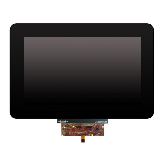
Kit Components Description DSAM-101JDHX30BP1U1 1280x800 TFT lcd with LVDS interface & ROCKTOUCH 10.1”W 3 mm USB Pcap Touch Screen TFC_UP2DSI FutureLabs DSI-LVDS board CB_UP2USB8 USB Bridge Cable CBL-41-03-100-A DSI Cable 41 pins 4 bolts, 4 nuts, 4 screw CB_UP2IPEX101 LVDS Cable for TFT 10.1”W... - Page 4 Package KIT-07X0ETTX30003U1...
-
Page 5: Assembly Procedure
Assembly Procedure Bring the Display with touch and align from back side with the DSI converter board, open the 4 PINS ZIF connector on the DSI board After you plug in the 4 pins Touch FPC into the 4 pins ZIF connector, then bring the LVDS Cable and plug in the white connector side on DSI converter board then the Golden side on the Display... - Page 6 Assembly Procedure Open the DSI 41 Pin connector from the back side Then plug in the DSI Cable, make sure the contacts are on the TOP side After you plug in the DSI cable, your solution will look like the following picture...
- Page 7 Assembly Procedure Plug in the USB bridge Cable on the 10 pin side on the DSI board The USB Cable will look like this picture And then you can fix the 4 spacer with the 4 nuts Then plug in on the top the UP board and fix with the remain 4 screws and plug in the DSI and USB Cables...
- Page 8 Assembly Procedure Make sure cables are plug in correctly on the UP board Put the UP board on the Bottom side As following image. Connect the HDMI cable to an External LCD monitor and Plug in the power supply on the UP board...
- Page 9 Assembly Procedure Once the UP logo will show on the Monitor please press DEL and you will enter into the BIOS, once you are into the BIOS go on Chipset menu North bridge and select: MIPI Port: Enable Panel Type: 1280x800 for 10_1’W Select Save Changes and Reset, now you can disconnect the HDMI cable from UP board.
- Page 10 Assembly Procedure Done! You will see the panel light up and touch will work out of the box. For the best Touch behavior please connect the LCD metal Frame to the board Ground.
Need help?
Do you have a question about the KIT-101JDHX30BP1U1 and is the answer not in the manual?
Questions and answers