
Summary of Contents for Aspar OSG HS
- Page 1 OSG HS Çift Yönlü Hız Regülatörü Montaj, Kullanma ve Bakım Kılavuzu OSG HS Bi-Directional Overspeed Governor User Manual, Assembly and Maintenance Instruction...
- Page 3 OSG HS ÇİFT YÖNLÜ HIZ REGÜLATÖRÜ MONTAJ, KULLANMA VE BAKIM KILAVUZU...
-
Page 5: Table Of Contents
İÇİNDEKİLER 1. Kullanım Kılavuzu ....................6 1.1 Açıklamalar ve Çalışma Prensibi ..................6 1.2 Güvenlik Uyarıları .......................10 1.3 Asansör Güvenlik Ekipmanlarının Çalıştırılması Konusunda Talimatlar ....10 1.4 Teslim Alma ve Kontrol ..................... 11 1.5 Parça Listesi ......................... 12 1.6 Ürün Etiketi ve Tanım ......................13 2. Montaj ........................14 2.1 Hız Regülatörünün Yere Montajı ..................14 2.1.1. Makine Dairesi Montaj Şekli ..................14 2.1.2. Assembly Steps ......................15 2.2 Hız Regülatörü Halatı ve Gergi Kasnağı Montajı ............16 2.3 ... -
Page 6: Kullanım Kılavuzu
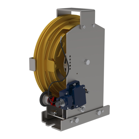
TİP OSG HS Min Nominal Çalışma hızı 2 m/s Max Nominal Çalışma hızı 3 m/s Rulmanlar Çift sabit bilyalı Rulman Yön Yukarı ve Aşağı Nominal Halat Çapı 6-8 mm Minimum Kasnak Çapı Ø300 mm Kaydırmasız, tampon etkili ve kaydırmalı fren Fren Bloku Tipi bloku ile kullanılmalıdır. 1. Kullanım Kılavuzu 1.1 Açıklamalar ve Çalışma Prensibi Hız regülatörü Asansör Direktifi 2014/33/EU ya göre güvenlik ekipmanıdır. Hız regülatörü nominal hızı %115 aştığı zaman, elektrikli güvenlik tertibati deveye girerek her iki taraftan kilitler. Bu durum sadece 1 m/s ve üzerindeki hızlar için geçerlidir. Diğer taraftan EN81-20 5.6.2.2.1.6 (a) da belirtildiği gibi, eğer hız 1m/s in altındaysa elektrikli güvenlik tertibatı frenleme hızından önce devreye girer. Merkezkaç kuvvet sayesinde, alt tarafta bulunan frenleme kolu kasnakta bulunan dişlerden birini frenletip ve kasnağın haraketini engelliyor. Halat ve kanal (V-ısıl işlemli altı kesik) arasında oluşan tahrik kuvvetleri fren bloğunu çalıştırıyor.Regülatör kasnağı-(1) altı kesik V kanal halatı kasnağa sarmak için. • Makara yolu (2) • Frenleme dişleri (3) • Halat koruma pimleri (4) • Frenleme Kolu (5) •... - Page 7 Regülatör halatı regülatör üzerinden dolanarak aşağıda gerdirme kasnağı üzerinden geçer ve halatlar fren blokuna sabitlenir. Gerdirme ağırlığı sayesinde halat istenen gerginliği sağlar ve regülatör üzerinde belli bir basınç ile halatı (1) nolu kanal üzerinden basar. Regülatör kasnağı üzerindeki (2) nolu makara yolu, üzreinde çalışan frenleme kolunun (5) sarkaç mantığı ile yukarı ve aşağı hareketini ...
- Page 8 ASANSÖR KUYUSU MAKİNA DAİRESİZ MONTAJ ŞEKLİ Hız regülatörünün kuyu içinde montaj edildiği durumlarda kolay ulaşılabilir bir yerde olmalıdır.
- Page 9 ASANSÖR MAKİNA DAİRELİ MONTAJ ŞEKLİ...
-
Page 10: Güvenlik Uyarıları
EN 81-50 3.20’de belirtildiği gibi, regülatörün montajı asansör konusunda deneyimli ve ehliyetli kişiler tarafından yapılmalıdır. Kılavuzda yazan bilgilere uyumsuz şekilde yapılan regülatör montajlarından ASPAR ASANSÖR A.Ş. sorumlu değildir. Taşınma esnasında regülatörün çalışmasını engelleyecebilecek hasarlar meydana gelebilir. Hasarlı regülatörler kullanılmamalıdır. Teknik güvenlik sebepleri ile, aşağıdaki durumlara izin verilmemelidir. a) Amacından farklı uygulamalarda kullanılır ise üretici ve firma sorumluluk kabul etmez. b) Belirtilen hıza uygun ürün seçilmelidir. c) Hız regülatörü parçaları değiştirilemez veya çıkartılamaz. 1.2 Güvenlik Uyarıları Montaj yapan firma, montajcının güvenliğinden sorumludur. Kitapçıktaki uyarılar dikkate alınmalıdır. DİKKAT! Tehlike uyarısıdır. Montaj yapan kişiye bağlı olarak risk taşıyan açıklamalardır. TEHLİKE! Bu sembol, ilgili kişilerin sağlık ve hayatlarının risk altında olduğunu gösterir. Her zaman bu uyarılara dikkat edilmelidir. Gerekli ve önem arz eden açıklamalardır Bu işaretler bu kılavuzun entegre bir parçasıdır. Kitapcığın kolayca ulaşılabilir bir yerde bulundurulması gerekir. Örneğin makine dairesi uygun bir yerdir. 1.3 Asansör Güvenlik Ekipmanlarının Çalıştırılması Konusunda ... -
Page 11: Teslim Alma Ve Kontrol
Bu yüzden montajına başlamadan önce bu kitapçıkta bulunan bilgilerin okunması ve iyice anlaşılması gereklidir. Güvenlik ekipmanlarının montaj ve kullanımı özel itina gerektirir. Çalışması için bu elemanların mükemmel çalışması gereklidir. Hız regülatörü imalatı sırasında yönetmenliğe uygun hızlara ve koşullara getirilir ve müşteriye teslim edilir. Regülatördeki ve gergi kasnağındaki siviçlerin işlevi kontrol edilir. Yanlış yapılan gergi kasnağı montajı sonucunda oluşabilecek hatalardan Aspar Asansör A.Ş. sorumlu değildir. 1.4 Teslim Alma ve Kontrol Parça listesi ile teslim aldığınız regülatörün parçalarını karşılaştırın. Parçalar size ulaştığı zaman, tüm parçaların size ulaşıp ulaşmadığını kontrol edin. Regülatörü sadece yere veya raya montajı yapılacak şekilde 300 mm’lik gergi kasnağı ile kullanılmalıdır. Sipariş verdiğiniz regülatörü, ürün üzerindeki etiketle kaşılaştırınız. -
Page 12: Parça Listesi
1.5 Parça Listesi Hız regülatörü Şekil 4 Gergi Kasnağı Şekil 5 Şekil 4 Şekil 5 Uzaktan kumandalı hız regülatörü Şekil 6 Gergi Kasnağı Şekil 7 Şekil 6 Şekil 7... -
Page 13: Ürün Etiketi Ve Tanım
1.6 Ürün Etiketi ve Tanım Ürün etiketi hız regülatörünün güvenlik bobini kısmı tarafında yerleşiyor. Ürün etiketi aşağıdaki bilgileri içeriyor: • Nominal Hız, • Frenleme Hızı, • Regülatör Tipi, • Üretim Tarihi, • Seri Numarası, • Belge Numarası, • CE Mark. Şekil 8... -
Page 14: Montaj
2. Montaj Makine dairesine giriş veya montajı sırasında aşağıdaki hususlar sağlanmalıdır. Makine dairesine ve kuyuya yetkisiz kişilerin girmesi engellenmeli ve tüm montaj ehliyetli kişiler tarafından yapılmalıdır. Kuyu içine regülatör montajı yaparken emniyet kemerinizi takınız. Makine dairesindeki delikleri kapatınız. Üzerinize düşme ihtimali olan makine dairesindeki takımlarınızı ve diğer çalışma aletlerinizi deliklerden uzaklaştırın. Makine dairesini kilitleyin ve asansör üzerine gerekli uyarı levhalarını koyunuz. 2.1 Hız Regülatörünün Yere Montajı 2.1.1. Makine Dairesi Montaj Şekli Hız regülatörünün beton üzerine veya bir tutucu üzerine montajı yapılabilir. Üzerine montajını yaptığınız beton ya da tutucu en az 30 kN basınca dayanıklı olmalıdır. Halatların kuyudan çıkıp makine dairesine geçiş yaptığı deliklerin mümkün olduğu kadar küçük olması ve en az 50 mm yüzük ile yükseltilmesi gereklidir. Şekil 9... -
Page 15: Assembly Steps
2.1.2. Assembly Steps Hız Regülatörü Şekil 10’de görüldüğü gibi monte ediniz. Şekil 10... -
Page 16: Hız Regülatörü Halatı Ve Gergi Kasnağı Montajı
2.2 Hız Regülatörü Halatı ve Gergi Kasnağı Montajı Hız regülatörünün teknik olarak doğru bir şekilde çalışabilmesi için halatın ve gergi kasnağının doğru bir şekilde entegre edilmelidir. Gergi kasnağı raya montajı yapılmalıdır. Şekil 11 Halatı kuyuya uygun uzunlukta kesin, gergi kasnağından dolandırın daha sonra gerekli bağlantı elemanlarını kullanarak fren bloğuna bağlayın. -
Page 17: Güvenlik Siviclerinin Montajı
2.3 Güvenlik Siviclerinin Montajı Elektrik siviclerini sadece eğitimli elektrik teknisyenleri tarafından yapılmalıdır. Bağlantıları yapmadan önce tüm elektrik tesisatını kapatınız. Emniyet sivici kablolarının ilgili standartlara uygun kullanılması gereklidir. Emniyet siviclerinin bağlantıları yapılmalıdır. 3. Çalışma Testi Üretici firma regülatörün testlerini yapmış olmasına rağmen montaj sırasında çıkabilecek aksaklıkları görmek için regülatör tekrar test edilmelidir. Fren blokları için gerekli ise test yapmadan önce rayları yağlayın. Asansörü revizyon konumuna alıp kuyu boyunca çalıştırın. Asansörün problemsiz olarak seyir yapabildiğinden emin olun. En alt ve en üst seviyelerde regülatör kasnağının ve gergi kasnağının üzerine bağlantı aparatlarının değmediğini gözlemleyin. Düşük hızda (revizyon konumunda) asansörü yukarıya/aşağıya çalıştırın. Bu sırada frenleme kolunu tornavidayla şekilde gösterildiği gibi aktif edin. Elektik kontağını kestiğini gözlemleyin. Arkasından bir miktar hareket ettirerek fren bloku kollarını çalıştırdığından emin olun. Daha sonra sistemi eski konuma getirin. Şekil 12... -
Page 18: Gergi Kasnağı
4. Gergi Kasnağı Gergi kasnağı sadece raya montaj edilmelidir. Montaj bitiminden sonra, ağırlık (25 kg) serbest bırakılmalıdır. 5. Uzaktan Kontrol Sistemi Makina dairesi olmayan kuyularda veya regülatöre ulaşmanın mümkün olmadığı durumlarda kullanılabilir. Frenleme ve başlatma için ayrı ayrı bobin mevcuttur. 5.1 Montaj a) Uzaktan kontrol sistemi regülatör üzerinde monteli olarak gelecektir. İmalatçı firma bilgisi olmadan müdahale edilmemelidir. b) Uzaktan kontrol sistemi 24 VDC ve 190 VDC olarak iki ayrı voltaj seçeneğine sahiptir. Panonuz için uygun voltaj tipini seçtiğinizden emin olunuz. c) Uzaktan kontrol sistemi, rahat çalışabilmek için asansör kuyu boşluğunun müdahale kapısına yakın bir yere tesis edilmesi sağlanmalıdır. Kablo bağlantıları için regülatör üzerinde bulunan klemensi kullanınız. -
Page 19: Güvenlik Bobinin Ve Siviçinin Bakımı
Şekil 14 5.2 Güvenlik Bobinin ve Siviçinin Bakımı Bakım talimatları EN 13015’e uygun bir şekilde yapılmalıdır. Güvenlik bobini ve siviçi her 6 ayda bir düzenli kontrol edilmelidir ve hız regülatörü kullanma klavuzu arka sayfasındakı bakım kayıt formuna işaretlenmelidir. • Fiziki hasarları kontrol ediniz • Elektrik bağlantı kablolarını kontrol ediniz • Eğer var ise kurtarma mekanizmasının çalışıp çalışmadığını kontrol ediniz. -
Page 20: Hız Regülatörü Koruması
OSG HS EN81-20 standartları dahilinde en az 20 kez kilitlemeye karşı garantilidir. Ayrıca kullanım kılavuzunda belirtilen şartlar içerisinde 2 yıl garantilidir. Aşağıda bulunan durumların bir veya birkaçına bağlı olarak meydana gelebilecek maddi ve manevi zararlardan Aspar Asansör A.Ş. sorumlu değildir. a) Kullanım kılavuzu veya standartlara aykırı montaj ve bakım ... -
Page 21: Hız Regülatörünün Bakımı
e) Herhangi bir şekilde parçalar üzerinde oynama yapılması. f) Beyan hızı dışında kullanılması. g) Gergi makarasının ağırlığının kılavuzda belirtilenden az ya da çok kullanılması. h) Dış etkenlere bağlı oluşan hasarlı regülatörlerin kullanılması. 8. Hız Regülatörünün Bakımı TİP OSG HS her 6 ayda bir düzenli olarak aşağıdaki kontrollere tabii tutulmalı ve arka sayfadaki bakım kayıt formuna işlemelidir Halatı uzamaya ve aşınmaya karşı kontrol edin. Halatın fren bağlantı noktalarını kontrol edin. Regülatör halat kanalının ve gerdirme ağırlığı kanalını kontrol edin. Kanal üst çapı ve halat arasındaki mesafe 3mm’den fazla olduğunda regülatörü ve gergi kasnağını değiştirin. Halat kanalının temizliğini kontrol edin. Fren kolu makarası üzerindeki O-ring lastiğini kontrol edin. Aşınma olmuş ise değiştirin. Regülatör halatının yağlı olmaması gereklidir. Yağlanmış ise temizleyin. Her ne sebeple olursa olsun, asansörün hız regülatörünü devre dışı bırakarak çalıştırmak kurallara aykırıdır. Regülatör üzerine herhangi parça takılamaz. - Page 23 OSG HS USER MANUAL, ASSEMBLY AND MAINTENANCE INSTRUCTIONS...
- Page 25 CONTENTS 1. User Manual ......................26 1.1 Explanations and Working Regulations ................26 1.2 Safety Precautions ......................30 1.3 Working Instructions of Safety Equipment ..............30 1.4 Delivery and Control ......................31 1.5 List of Parts ..........................32 1.6 Name Plate, Designation and Identification ...............33 2. Assembly ......................33 2.1 Assembly of The Overspeed Governor On The Floor ..........34 2.1.1. . Assembly In The Machine Room ................34 2.1.2. Assembly Steps ......................35 2.2 ...
-
Page 26: User Manual
TYPE OSG HS Min Adjustable Nominal Speed 2 m/s Max Adjustable Nominal Speed 3 m/s Bearings From two sides ball bearings Direction Up and down Nominal Rope Diameter 6, 6.5, 8 mm Minimum Governor Pulley Dia Ø300 mm Use with progressive safety gears and Safety Gear Type instantaneous safety gear with buffer effect. 1. User Manual 1.1 Explanations and Working Regulations The overspeed governor is a safety device according to Lift Directive 2014/33/EU. When the overspeed governor exceeds to its nominal speed by 115%, the contact locks the overspeed governor for both directions. This condition applicable for the speed equal or greater than 1 m/s. On the other hand, as stated in 5.6.2.2.1.6 a of EN 81-20, if the speed is below 1 m/s, the contact locks the overspeed governor before tripping speed. Because of centrifugal forces the pendulum leaver located on the bottom, will trip on one of the cams and block the pulley both upwards and downwards. The traction forces between the rope and (V-hardened with undercut) groove will activate the safety gear. • Governor Pulley-(1). With undercut V groove to house the over speedgovernor • Cam rim (2) •... - Page 27 The rope, secured to the clamp of the safety gear and stretched, operates the governor pulley through its own pressure in the undercut groove (1). The square shaped path (2), which is on the pulley (1) moves the pendulum lever (5) slightly up and down. The pendulum lever is forced to move on the path by a spring and the spring is protected against any adjustments by cover plastic. The plastic cover is mounted on the overspeed governor by using screws and it is painted. When the centrifugal force exceeds the spring force, the pendulum lever impacts on the cam-notches (3). Moreover, the pulley (1) is blocked and before braking, the switch is activated and safety circuit of the plant is switched off. The rope protection retainer (4) prevents the rope to come out from the groove. The undercut angle of the groove is 68.53 degrees and groove angle is 35 degrees. As stated in EN 81-50, undercut angle should be equal or greater than 35 degrees and the groove angle should be equal or less than 105 degrees. The overspeed governor is compatible according to the rules and regulations for EN 81- 20/50...
- Page 28 POSITION ON TOP OF THE ELEVATOR SHAFT For the assembly on the top of the elevator shaft, the overspeed governor must be easily accessible from the outside.
- Page 29 POSITION IN THE ENGINE ROOM...
-
Page 30: Safety Precautions
The installer, who is well trained with assembly of safety equipment, must performed required action as stated in 3.20 of EN 81-50. Aspar Asansör A.Ş declines any responsibility that have not been carried out according to this guide. During the transportation, the overspeed governor can be damaged. Never use damaged products. Because of the technical safety rules, pay attention followings; a) Manufacturer is not responsible for the products that is not used on its purpose. b) Choose the product according to the declared speed. c) The overspeed governor parts cannot be changed or removed. 1.2 Safety Precautions The assembler company is responsible for the safety of the installer. They should consider warnings in the guide. WARNING! Indication of the danger of the possible damages to the structural elements and its components parts. Maybe cause for the injuries and serious product damages. DANGER! This symbol shows that health and life of the related persons are under risk. Always, pay attention to warnings. Indication of useful information These instructions are an integral part of this guide it must be kept in an easily ... -
Page 31: Delivery And Control
For that reason, the user manual must be read and understood before assembly. Safety devices need particular attention. Their perfect functioning is essential for a safe operation of the plant. As a safety, devices are already preset at the factory and their operations must be carried out immediately after the assembly itself. The functioning of safety switches on the governor and on the tension pulley must be checked. Aspar Asansör A.S is not responsible of the wrong assembled tension pulley. 1.4 Delivery and Control Compare the list of the parts that you purchase the overspeed governor. When you receive the parts, check the list whether you received all parts completely or not. Use the overspeed governor only when mounting on the guide rail of 300 mm tension pulley. Compare the overspeed governor that you ordered, with the data label that mounted on the product. -
Page 32: List Of Parts
1.5 List of Parts Overspeed governor Figure 4 Tension Pulley Figure 5 Figure 4 Figure 5 Overspeed governor with the remote control system Figure 6 Tension Pulley Figure 7 Figure 6 Figure 7... -
Page 33: Name Plate, Designation And Identification
1.6 Name Plate, Designation and Identification The data label of the overspeed governor is located on UCMP feature side. The data label gives you following information: • Nominal Speed, • Tripping Speed, • Type of the governor, • Production date, • Serial Number, • Certificate Number, • CE Mark. 2. Assembly Figure 8... -
Page 34: Assembly Of The Overspeed Governor On The Floor
For all the assembly process, in the engine room or in elevator shaft, it should be made clear. The entrance into machine room and shaft bottom are only allowed for installer and maintenance staffs. During assembly, safety belts should be used. In order to secure the assembly tools and other objects from fallings, cover the hole in the floor of the machine room. Machine room door must be locked and provided with a warning sign. 2.1 Assembly of The Overspeed Governor On The Floor 2.1.1. Assembly In The Machine Room The assembly of the overspeed governor can be performed easily on a floor. Floor and support must resist a load of min 30kN The rope aperture should be kept as small as possible and fitted with a 50 mm high collar. A corresponding safety collar must be fastened to the floor before installation takes place. Figure 9... -
Page 35: Assembly Steps
2.1.2. Assembly Steps You should assemble overspeed governor as shown the Figure 10 Figure 10 Maintenance door should be made in order to access easily to the overspeed governor in elevator shaft. -
Page 36: Assembly Of The Overspeed Governor's Rope And Tension Pulley
2.2 Assembly of The Overspeed Governor’s Rope and Tension Pulley A fully operation of the overspeed governor is only possible with a correct assembly of the governor rope itself and the tension pulley. Tension pulley can be mounted only on the guide rail. Figure 11 Cut the overspeed governor rope to appropriate length and wrap it around of pulley of the tension pulley and governor’s pulley. By using proper tools, mount the rope to the system. -
Page 37: Assembly Of The Safety Switches
2.3 Assembly of The Safety Switches The specialized electricians should perform assembly process. Before beginning operations, turn off the power of all the parts of the plant. All safety switch cables required to be accordance with EMV rules and regulations. Connection of safety switches must be made. 3. Operation Testing Although manufacturer tested product before sale, the speed governor must be re-tested to see any problems during the assembly process. Before performing the test, if necessary, the guide rails should be oiled for the safety gears. Bring the lift into the overhaul position and run it along the lift shaft. Be sure that lift works without problem. At the lowest and highest level, observe both pulley of the overspeed governor and tension pulley to be sure whether any collision with connection apparatus occurs or not. With a slow speed upwards and downwards, activate the overspeed governor by a screwdriver as shown in the figure. Check the safety switch it is working normally. In addition, check if safety gears works. Later, bring the system into previous position. Figure 12... -
Page 38: Tension Pulley
4. Tension Pulley Tension pulley can be connected to only guide rail. After mounted the tension pulley to the guide rail correctly, the weight (25kg) could be released. 5. Remote Control System It should be used if there is no engine room in the wellhole or reaching the overspeed governor is impossible. Separate coils exist for both activating and tripping. 5.1 Assembly a) Remote control system is to be delivered as assembled on overspeed governor and it should not be interfered without informing the manufacturer company. b) Remote control system has two type voltage options as 24VDC and 190VDC. You should be sure that you choose the appropriate one for your panel. c) In order to run remote control system easily, it should be assembled nearby area of interfere door of the wellhole. You should use connector that is on overspeed governor for cable connections... -
Page 39: Maintenance Of Safety Coil And Switch
Figure 14 5.2 Maintenance of Safety Coil and Switch Maintenance instructions are in compliance with EN 13015. Safety coil and safety switch must be checked every 6 months and any comments must be noted on maintenance registration form on MOUNTING, OPERATION and MAINTANENCE MANUAL. • Check damaged conditions • Check the electric connection points of the safety coil • If there is rescue mechanism, it must be check whether it is working or not. -
Page 40: Protection Of Overspeed Governor
6. Protection of Overspeed Governor There is only one type protection cover for the overspeed governor. It consist of 2mm plastic and assembled by using two screws. Figure 15 7. Warranty Regulations and Responsibility According to EN81-20 standards, the TYPE OSG HS is locked minimum 20 times under warranty. The product has warranty for 2 years. Aspar Asansör A.S is not responsible for the damages in following situations. a) If the component part is used in a different way than described in this book. b) Even though the overspeed governor is damaged, continued to use it. c) Not used on purpose d) Changing the tripping speed or removing the seal... -
Page 41: Maintenance Of The Overspeed Governor
e) Changing any of the parts with another f) Not used on declared speed g) Not tensioned rope sufficiently h) Using damaged overspeed governor, which caused due to external effects. 8. Maintenance of The Overspeed Governor The TYPE OSG-M must be checked every 6 months and comments must be noted on the Maintenance registration form. 1. Check ropes. If it worn, change it. Check ropes. If it loosen, tensioned them. Check rope and safety gear connection points. Check the grooves and tension pulley, if the distance between groove diameter on the top and the rope is more than 3mm, change the overspeed governor and tension pulley. Check cleanliness of the rope grooves. Check the O-ring on the catch lever. Change it, if deformed. If overspeed governor rope is oily, it must be cleaned. For whatever reason it might be, it is not allowed to operate elevator without the speed governor. ... - Page 45 BAKIM KAYIT FORMU MAINTENANCE RECORD FORM Tarih / Date Arıza Bakım Notları / Description KİLİTLEME KAYIT FORMU RECORD FORM OF LOCKINGS Operatör Adı Soyadı Tarih/Date Kilitleme Nedeni / Reason of Locking Name of the operator...
- Page 46 BAKIM KAYIT FORMU MAINTENANCE RECORD FORM Tarih / Date Arıza Bakım Notları / Description KİLİTLEME KAYIT FORMU RECORD FORM OF LOCKINGS Operatör Adı Soyadı Tarih/Date Kilitleme Nedeni / Reason of Locking Name of the operator...
- Page 47 BAKIM KAYIT FORMU MAINTENANCE RECORD FORM Tarih / Date Arıza Bakım Notları / Description KİLİTLEME KAYIT FORMU RECORD FORM OF LOCKINGS Operatör Adı Soyadı Tarih/Date Kilitleme Nedeni / Reason of Locking Name of the operator...
- Page 48 BAKIM KAYIT FORMU MAINTENANCE RECORD FORM Tarih / Date Arıza Bakım Notları / Description KİLİTLEME KAYIT FORMU RECORD FORM OF LOCKINGS Operatör Adı Soyadı Tarih/Date Kilitleme Nedeni / Reason of Locking Name of the operator...
- Page 49 BAKIM KAYIT FORMU MAINTENANCE RECORD FORM Tarih / Date Arıza Bakım Notları / Description KİLİTLEME KAYIT FORMU RECORD FORM OF LOCKINGS Operatör Adı Soyadı Tarih/Date Kilitleme Nedeni / Reason of Locking Name of the operator...
- Page 50 BAKIM KAYIT FORMU MAINTENANCE RECORD FORM Tarih / Date Arıza Bakım Notları / Description KİLİTLEME KAYIT FORMU RECORD FORM OF LOCKINGS Operatör Adı Soyadı Tarih/Date Kilitleme Nedeni / Reason of Locking Name of the operator...
- Page 51 BAKIM KAYIT FORMU MAINTENANCE RECORD FORM Tarih / Date Arıza Bakım Notları / Description KİLİTLEME KAYIT FORMU RECORD FORM OF LOCKINGS Operatör Adı Soyadı Tarih/Date Kilitleme Nedeni / Reason of Locking Name of the operator...
- Page 52 Barbaros Cd. No:18 ASO 2-3 OSB T: 0312 534 17 31 Yukarı Dudullu 2032 Cad. No:13 F: 0312 354 64 80 Ümraniye/İstanbul Temelli/Ankara aspar@aspar.com T: 0216 313 06 53 T: 0312 557 08 07 F: 0216 314 38 40 istanbul@aspar.com www.aspar.com...
Need help?
Do you have a question about the OSG HS and is the answer not in the manual?
Questions and answers