Advertisement
Quick Links
HYDRA 120 & HYDRA 240 OPERATION MANUAL
Thank you for purchasing the most technologically advanced brushless electronic
speed controller in the world for RC boats! Please take the time to read over these
instructions to ensure you get the most from your HYDRA brushless speed control,
and enjoy years of trouble-free operation.
1.0 Features of the HYDRA™ :
Extremely Low Resistance (120 is .00043 ohms; 240 is .00022 ohms )
•
•
Up to 120 or 240 Amps continuous current
Water cooled heat sinks (see section 6.0 below)
•
•
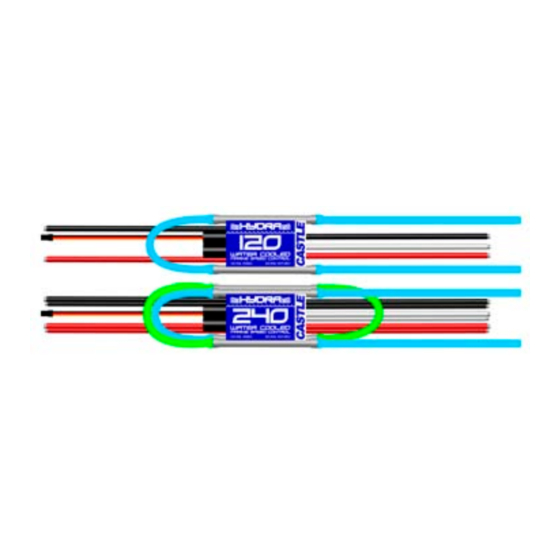
Massive 10 gauge wire on Hydra 120 and double 10 gauge wires on
the Hydra 240.
12 cells (3s lipo) MAX with BEC
•
Six to twenty cells, or 2 to 6 cell Lithium Polymer packs
•
BEC (3A) provides power to receiver and
•
servo - eliminates separate receiver battery
User Programmable Features:
•
·
Reverse Type
·
Reverse Throttle Amount
·
Low voltage cutoff (LiPo safe)
·
Timing Advance
·
Starting Power
Safe "power on" arming program helps prevent motor from accidentally
•
turning on. Always use extreme care with high power systems.
Auto shut down when signal is lost or radio interference becomes severe.
•
2.0 Making Connections on your HYDRA™ speed control
Tools required:
Wire cutters
Wire stripper (optional)
Soldering iron (30-40W)
2.1 Adding a battery connector to your HYDRA™:
HYDRA 120 & 240 User Guide
This document, HYDRA™ software, and HYDRA PCB layout are all Copyright © 2004-2007 by Castle Creations, Inc.
Parts required:
Rosin core electrical solder
Battery connector
The battery connector must be added to the power side of the controller (black
capacitors, receiver connector, and red and black wire side). The red wire is the
positive (+) lead, and must match up to the positive lead from your battery. The
black wire is the negative (-) lead, and must match up to the negative lead from
your battery. The polarity MUST BE CORRECT or the controller will be damaged
from reversed polarity.
The Hydra 240 has two SETS of input and output wires. We recommend using a
separate connector for each connection to ensure maximum current capacity.
Make sure and connect the entire battery pack to both input wire sets of the Hydra
240. Do not connect half of the pack to one input, this will lead to operating
problems from potential voltage / current imbalances.
Strip just enough insulation off of the battery wires to solder on your battery
connector to the controller leads. After the connector is soldered and insulated
(shrink tubing or electrical tape) check it ONE MORE TIME to make sure the
polarity is correct before you plug in a battery.
2.2 Plugging in motor leads:
With a brushless system, there is no polarity on the MOTOR side of the controller.
Simply solder the three leads to your motor (recommended) or solder your choice
of connectors to the motor and controller leads. After the throttle calibration routine
below – if the motor runs backwards with forward throttle, simply swap any two of
the motor/controller connections and it will reverse the rotation of the motor.
The Hydra 120 and 240 controllers are designed to control one motor. Do not
attempt to drive two motors with the Hydra 240. Connect the dual outputs of
the 240 to a single motor's leads.
2.3 Connecting to the receiver:
Connect the receiver lead (the three color wires with a connector on the end) to the
throttle channel on your receiver (usually channel 2). Do not connect a battery to
the receiver, as the HYDRA™ will supply power to the receiver and servo through
the receiver connector. If you are using more than 12 cells, or 3s Lipo packs, the
BEC must be disabled on the controller. Disable the BEC by removing the red wire
from the receiver connector. Use a separate battery pack or switching BEC (like
our CC BEC) to power the servos and receiver after disabling the BEC.
3.0 Calibrating the HYDRA™ to YOUR transmitter:
IMPORTANT NOTE: Calibration is required for the very first use of the
HYDRA™, after updating software using the Castle Link USB programmer, or
whenever used with a new/different transmitter.
The HYDRA™ contains a throttle calibration feature that you'll want to use the first
time you power it up with a new/different transmitter. Performing this exercise will
Page 1 of 5
Rev 8-date 10/25/07
Advertisement

Summary of Contents for Hydra 120
- Page 1 Performing this exercise will HYDRA 120 & 240 User Guide Page 1 of 5 Rev 8-date 10/25/07 This document, HYDRA™ software, and HYDRA PCB layout are all Copyright © 2004-2007 by Castle Creations, Inc.
- Page 2 LED and emitting a beeping tone. Release the trigger allowing it to HYDRA 120 & 240 User Guide Page 2 of 5 Rev 8-date 10/25/07 This document, HYDRA™ software, and HYDRA PCB layout are all Copyright © 2004-2007 by Castle Creations, Inc.
- Page 3 (if it has them) are set all the way open (both top and bottom, are furthest from zero). HYDRA 120 & 240 User Guide Page 3 of 5 Rev 8-date 10/25/07 This document, HYDRA™ software, and HYDRA PCB layout are all Copyright © 2004-2007 by Castle Creations, Inc.
- Page 4 Please see the diagram below for reference. 7.0 Contact/warranty information: HYDRA 120 & 240 User Guide Page 4 of 5 Rev 8-date 10/25/07 This document, HYDRA™ software, and HYDRA PCB layout are all Copyright © 2004-2007 by Castle Creations, Inc.
-
Page 5: Programmable Features
4) 100% equal to 100% of full power HYDRA 120 & 240 User Guide Page 5 of 5 Rev 8-date 10/25/07 This document, HYDRA™ software, and HYDRA PCB layout are all Copyright © 2004-2007 by Castle Creations, Inc.
Need help?
Do you have a question about the 120 and is the answer not in the manual?
Questions and answers