Table of Contents
Advertisement
Quick Links
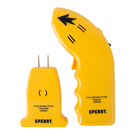
OPERATING INSTRUCTIONS
Model CS-550A
CIRCUIT BREAKER FINDER
A.W. SPERRY INSTRUMENTS INC.
The Professional's Choice™
8) SWITCH CONTROLED OUTLETS:
Because wall switches are sometimes used to control outlets, be sure to turn on these
switches prior to plugging in the transmitter.
9) BATTERY LIFE:
While powered, the receiver will consume 10ma from the battery. The L.E.D. in the receiver
will rapidly become dim when the battery voltage drops below 8 volts and will completely
extinguish at 7.5 volts. Replace the battery when the L.E.D. fails to light or becomes
noticeably dim. Turn off receiver when not in use to prolong battery life.
10) SPECIFICATIONS:
Working Voltage Range 80-140V max. to ground
Frequency: 50-60Hz
Operating Temperature: 32 to 122F(0-50C)
Storage Temperature: -4 to 158F(-20-70C)
Power Supply:
Receiver: One (1) 9V Transistor Type Battery (NEDA #1604) Part # B-4
Dimensions:
Transmitter: 3.3" H x 2.6" W x 1.1" D (83 x 67 x 28mm)
Receiver: 6.3" H x 3.4" W x 1.1" D (159 x 86 x32mm)
Weight:
Transmitter: 2.5 oz. (70g)
Receiver: 5.1 oz. (145g)
1) FEATURES:
• UL Listed to both US and Canadian Standards
• One Year Limited Warranty
• Locates AC Breakers or Fuses
• No need to interrupt power
• Distinctive signal
• Audible and visual indication
• Does not interfere with sensitive electronic equipment
1. Self-calibrating receiver with audible and visual indicators.
2. Self-powered transmitter with audible and visual indicators.
2) PREPARATION FOR USE
:
(figure 1)
1. Install a 9-volt alkaline battery (battery not included).
2. Reinstall battery cover.
3. Test battery by turning on unit (rocker switch)
4. L.E.D. will light brightly indicating the battery is in good condition.
3) TESTING THE TRANSMITTER AND RECEIVER
(figure 2)
1. Plug the transmitter into a powered electrical wall outlet.
2. L.E.D will flash and beeper will sound at approximately seven times per second.
3. Turn on receiver and place target on the tip against rear of transmitter (as shown).
4. Receiver L.E.D. will flash and beeper will sound in time with the
transmitter.
5. While continuing to hold receiver against rear of transmitter press
and hold calibration switch.
6. The receiver will stop responding with-in one to two seconds.
7. Release calibration switch, receiver will again respond
to the transmitter's signal.
8. This completes the test; turn off the receiver to reset the calibration circuit to full sensitivity.
4) LOCATING A CIRCUIT BREAKER
(figure 3)
:
1. With the transmitter plugged into an AC outlet to go the circuit breaker panel and open
the cover.
2. Turn on the receiver and place target on the tip firmly against the first circuit breaker in
the panel.
3. Press and hold the calibration switch while moving the receiver across the circuit breakers.
Test Equipment Depot - 800.517.8431 - 99 Washington Street Melrose, MA 02176
4. When the receiver responds to a circuit breaker stop movement until the receiver stops
responding, then continue moving the receiver to the next breaker.
5. During the calibration process the receiver may respond to more than one of the circuit
breakers in the panel, each time this occurs wait for the receiver to stop responding before
moving to the next circuit breaker.
6. After scanning all the circuit breakers in the panel release the calibration switch and rescan
the circuit breakers.
7. Only one breaker will now produce a response in the receiver.
8. While continuing to hold the receiver against this breaker turn off the breaker, this will
remove power to the remote transmitter and the receiver will cease producing a response.
This confirms that the transmitter is no longer receiving power.
9. Turn off receiver; additionally this resets the calibration circuit if
another scan is desired.
10. Always confirm that power to the outlet has been removed by
noting the absence of sound and light when in the presence of
the transmitter.
11. Unplug transmitter when not in use.
FIG. 1
:
5) OVERHEAD LIGHTING:
The circuit breakers controlling ceiling lights may also be identified
by using a light socket adaptor or socket to clip lead adaptor such
as the Sperry CSA-300A Adapter Set (sold separately) as shown
in figure 4.
6) SAFETY NOTE:
Since the routing of electrical wiring in the home can take many forms, it is possible for
additional hot wires controlled by different circuit breakers to be present in the outlet box.
Because of this possibility, it is recommended that an AC Voltage Sensor such as the
FIG. 2
Sperry Model VH-601A (sold separately) be used to test for the presence of additional hot
wires in the outlet box prior to performing any work inside the box.
7) LIGHT DIMMERS:
High power light dimmers may interfere with the operation of the unit by giving a false
response when scanning the circuit breaker panel. The presence of such a light dimmer will
produce a much higher flash and beep rate from the receiver compared to the normal rate of
seven times per second. It is recommended that any dimmers in operation be set to full
power, or shut off when using the Circuit Breaker Finder.
TestEquipmentDepot.com
FIG. 3
FIG. 4
Advertisement
Table of Contents

Subscribe to Our Youtube Channel
Related Manuals for Sperry instruments CS-550A

Summary of Contents for Sperry instruments CS-550A
- Page 1 8. This completes the test; turn off the receiver to reset the calibration circuit to full sensitivity. wires in the outlet box prior to performing any work inside the box. A.W. SPERRY INSTRUMENTS INC. 4) LOCATING A CIRCUIT BREAKER (figure 3) 7) LIGHT DIMMERS: The Professional’s Choice™...
Need help?
Do you have a question about the CS-550A and is the answer not in the manual?
Questions and answers