Table of Contents
Advertisement
Quick Links
Advertisement
Table of Contents

Related Manuals for Tescom TC-5062C


Summary of Contents for Tescom TC-5062C
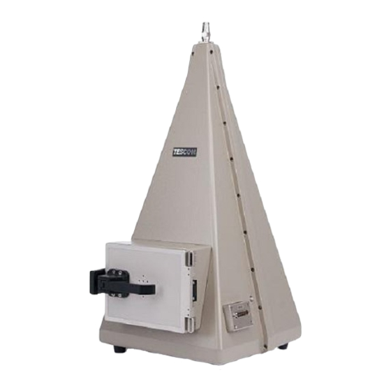
- Page 1 TC-5062C 6 GHz TEM Cell Operating Manual R121114 http://www.tescom.co.kr Information contained in this document is subject to change without notice. Copyright © 2012 Tescom Co., Ltd. Suite #927, Unitechvil 142, Ilsan-ro, Ilsandong-gu, Goyang-si, Gyunggi-do, Korea.
- Page 2 Blank Page...
-
Page 3: Table Of Contents
3.1 Maintenance of TC-5062C ....................20 3.1.1 Cleaning ..........................20 3.1.2 Check List for Maintenance ....................20 3.2 Performance Test ......................22 3.2.1 Calibration Period ........................22 3.2.2 Required Equipment ......................22 3.2.3 Test Procedure ........................22 3.2.4 Typical VSWR of TC-5062C ....................24... - Page 4 [Figure 3] Field Generation and Field Pattern ..............17 [Figure 4] Radiation Power Measurement ..............18 [Figure 5] TC-5062C RF Gasket ..................21 [Figure 6] TC-5062C Shielding Measurement Test Set Up ..........22 [Figure 7] Spectrum Analyzer Display ................23 [Figure 8] Typical VSWR of TC-5062C ................24 Table of Contents [Table 1] TC-5062C Connectors ..................
-
Page 5: Warranty
TESCOM responsibility to repair or replace deductive products is the sole and exclusive remedy provided to the customer for breach of this warranty. TESCOM will not be liable for any indirect, special, incidental, or consequential damages, despite any advance... -
Page 6: Safety Considerations
Safety Considerations Safety Considerations Review the following safety precautions to avoid injury and prevent damage to this product or any product connected to it. Do Not Disassemble any part except replaceable parts Do Not Operate in Wet/Damp Conditions To avoid injury or fire hazard, do not operate this product in wet or damp conditions. -
Page 7: Service And Support
Service and Support Service and Support If you have a problem with your TC-5062C, contact Tescom Technical Support specialists. Any adjustment or repair of this product must be performed by qualified personnel. Contact Information Address: TESCOM Company Limited, #927 Unitechvil 142, Ilsan-ro, Ilsandong-gu, Goyang-si,... - Page 8 Service and Support Blank Page...
-
Page 9: General Information
1. General Information Chapter General Information This section provides a general description of the 6 GHz TEM cell and proper set-up procedures. -
Page 10: Instructions And Key Features
WLAN, PDA, Bluetooth, DAB/DMB, RFID, etc. Through the RF input/output port, an external test signal may be applied to the TC-5062C to generate a predictable TEM test field inside the cell. The radiation field can also be picked up through the RF input/output port using a test receiver. -
Page 11: Connectors
1. General Information 1.3 Connectors This section contains reference information for TC-5062C’s connectors. [Table 1] TC-5062C Connectors Connector Specification Impedance: 50 ohm N Coaxial Connector Voltage Rating: 1500 Vpeak Dielectric Withstanding Voltage: 2500 Vrms Impedance: 50 ohm Voltage Rating: 250 Vpeak... -
Page 12: Initial Inspection
1. General Information 1.5 Initial Inspection 1) Upon receipt of the TC-5062C, check for any damages that could have occurred during shipment. 2) Verify you have received the accessories supplied with the TC-5062C and module, which are listed in Table 2, 3. -
Page 13: F50621A Dut Rotator Component Identification
1. General Information 1.6 F50621A DUT Rotator Component Identification [Figure 2] F50621A DUT Rotator Component Identification ① Handle ② Rotary Knob for rotating DUT ③ Rotation Angle Plate ④ DUT Holder: Fix the DUT in proper position. The DUT can be measured at different direction by rotating the rotator handle. -
Page 14: Storage
1. General Information 1.7 Storage The storage temperature range for this equipment is –20 C to 70 C. When this equipment is not used for a long period of time, cover with vinyl or place in a cardboard box and store in a dry place away from direct sunlight. - Page 15 Chapter Operation This section provides important information regarding TC-5062C operation...
-
Page 16: Theory Of Operation
E (Volt/meter) = V (Volt) / L (meter) ………………… (1). Here, L is the distance between the septum and the top wall. In TC-5062C, L is 22 (cm). Since TEM Cell produces a TEM wave, an orthogonal H-field (ampere/meter) proportional to E-field exists. They are related by the free sp H (Ampere/meter) = E (Volt/meter) / 377 (Ohm) .. - Page 17 [Figure 3] Field Generation and Field Pattern <Example> Connect the RF output of a signal generator to the input port of TC-5062C with a cable. Set the signal generator frequency (between 100 MHz to 6 GHz) and the signal level to 220 mV.
-
Page 18: Radiation Power Measurement (Ref.2, Figure 4)
2. Operation 2.1.2 Radiation Power Measurement (Ref.2, Figure 4) When a radiating object is placed inside the TEM cell, the radiated power Po (Watt) travels equally to both ends of TEM cell. The voltage measured, Vm (Volt) at one end can be expressed as follows: Vm (Volt) = SQRT (Po x Zo/2) ……………....... -
Page 19: Maintenance
Chapter Maintenance This section contains information for keeping the instrument in good working order and checking its overall performance. -
Page 20: Maintenance Of Tc-5062C
3. Maintenance 3.1 Maintenance of TC-5062C The TC-5062C is designed and built to last for a long life and with minimal and easy maintenance. Optimal RF shielding is obtained using a shield form gasket between the case and door. It must be checked periodically for any damage or excessive wear that would compromise the seal. - Page 21 [Figure 5] TC-5062C RF Gasket Do not clean this equipment with organic solvents such as benzene, toluene or acetone as they will damage the plastic parts. Use alcohol to clean and maintain parts of the equipment.
-
Page 22: Performance Test
Network Analyzer: 6 GHz Signal Generator: 6 GHz Dipole Antenna: Tescom 900 MHz, 1.8 GHz, 2.4 GHz, 5.8 GHz 3.2.3 Test Procedure Shielding Effectiveness Measurement Specification: > 80 dB up to 2 GHz, > 70 dB 2 GHz ~ 3 GHz, > 60 dB 3 GHz ~ 6 GHz... - Page 23 4) Connect the 900 MHz Dipole antenna to the Spectrum Analyzer with RF cable. 5) Open the door of the TC-5062C and move the antenna around the TC-5062C to find the location where the maximum field is found. Fix the location of antenna for maximum field.
-
Page 24: Typical Vswr Of Tc-5062C
Format: SWR 2) Calibrate the Network Analyzer in order to measure S11. 3) Connect the calibrated cable to the input port of TC-5062C and measure SWR. 4) Verify S11 SWR of-5062C meets its specification. 3.2.4 Typical VSWR of TC-5062C...
Need help?
Do you have a question about the TC-5062C and is the answer not in the manual?
Questions and answers