
Related Manuals for Kikusui PLZ-3WH Series


Summary of Contents for Kikusui PLZ-3WH Series
- Page 1 Electronic Test Instruments & Power Supplies ELECTRONIC LOAD PLZ-3WH SERIES PLZ153WH PLZ303WH PLZ603WH PLZ1003WH Operation Manual Part No. Z1-002-502 IB003003...
- Page 2 If you find any incorrectly arranged or missing pages in this manual, they will be replaced. If the manual it gets lost or soiled, a new copy can be provided for a fee. In either case, please contact Kikusui distributor/ agent, and provide the “Kikusui Part No.”...
-
Page 9: Table Of Contents
Contents 4.4.5 Saving and Calling Set Values ..................4-18 4.4.6 Switching Function ....................... 4-21 4.4.7 Keylock Function ......................4-23 4.4.8 Setup Function and Backup Memory ................4-24 4.4.9 Configuration ........................ 4-26 4.4.10 Alarm ..........................4-28 4.4.11 Short Function ......................4-29 4.5 Sequence Operation ........................ - Page 12 Chapter 1: General General The PLZ-3WH series electronic load unit is a multifunctional system designed to offer the highest levels of safety and reliability. This load unit contains a high-performance current control circuit to ensure stable, high-speed operating performance. In addition, its CPU control feature works to improve operability and multifunctional capability.
- Page 13 Chapter 1: General Operation Manual and ROM Version This manual applies to products equipped with any of ROM versions 2.00 to 2.09. When contacting us with a question about one of our products, please provide us with the following information concerning the product: - Type - ROM version...
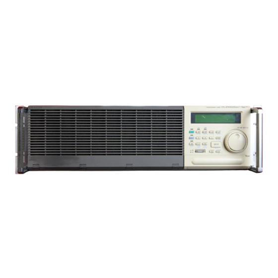
- Page 32 Chapter 3: Designations and Basic Functions of Controls 3.1 Front Panel Layout Air inlet Auxiliary load terminals Handle Handle Air inlet ...
- Page 34 Chapter 3: Designations and Basic Functions of Controls Display CC and CR lamps Arrow keys LOAD switch Jog-Shuttle Function keys POWER switch Subpanel 4 4 4 4 4 POWER switch Whenever you press this switch, the load unit is turned on or off (depending on its current status). Since the load unit functions are automatically diagnosed after a power-on, you cannot operate the unit for about 2 seconds.
- Page 37 Chapter 3: Designations and Basic Functions of Controls Sequence keys • SEQ (IB STS) When you press this key, the sequence mode menu appears. If you press this key while also holding down the [SHIFT] key, the GPIB status display function (IB STS) is selected and the status appears on the display.
- Page 38 1 6 1 6 1 6 1 6 1 6 Manufacturing number The manufacturing number of your PLZ-3WH series electronic load unit. 1 7 1 7 1 7 Remote sensing connector 1 7 ...
- Page 41 Chapter 4 Operating Procedur This chapter describes basic functions and operating procedures of the load unit. Status of Display After Power-on ........... 4-2 Basic Operations on Front Panel ........... 4-3 Constant Current, Constant Resistance, Constant Voltage, and Constant Power Modes ..... 4-4 Basic Operating Procedure ............
-
Page 64: Setup Function And Backup Memory
Setup Function and Backup Memory The PLZ-3WH series electronic load unit automatically saves and maintains the setup status immediately before a power-off. You can also copy part or all of the set values listed below as setup values for backup purposes, so that the load unit can be easily set under various different conditions. - Page 65 Chapter 4: Operating Procedure ● ● ● ● ● Setup procedure (1) Press the [SHIFT] + [I SET] (SET UP) keys to select > 1: Initialize Setup the setup function. The first item of the setup Push [ENTER] function menu appears on the display. If you want only to initialize the setup values, press the [ENTER] key.
- Page 67 Chapter 4: Operating Procedure 9: Interface Selects each interface operating environment. 1: GPIB Address GPIB address (the default is address 1). 2: Power-on SRQ Power-on service request [Enable] [Disable] (default) 3: MCB Address MCB address (the default is 15). 4: RS-232C Speed Baud rate [9600 bps] (default)
-
Page 71: Description Of Sequence
The sequence operation automatically controls the current in an arbitrary waveform according to the time-dependent variation of certain predetermined mode settings (such as the ISET, RSET, VSET, and PSET values). On the PLZ-3WH series electronic load unit, the sequence operation can be programmed, saved to the built-in backup memories, and recalled for later execution. - Page 72 Chapter 4: Operating Procedure For set values other than the mode settings that will be subject to sequence operation, the values immediately before execution of the sequence operation are maintained. For example, when you want to execute a sequence operation for the ISET value in NI mode, the PSET and VSET values from immediately before execution of the sequence operation are maintained.
- Page 73 Chapter 4: Operating Procedure (b) Step, program and sequence ● ● ● ● ● Step A “step” is the most basic unit of the sequence operation, and the sequence is executed from the first step. The items listed in Table 4.5-1 are set for each step. In a normal-speed sequence, the step execution time and pause function can be set for each step.
-
Page 77: Outline Of Sequence Operation Setup
Chapter 4: Operating Procedure 4.5.2 Outline of Sequence Operation Setup To set the sequence operation, sequence file management is required, along with creation and editing of sequence parameters. For information on this setup procedure, see Section 4.5.3, “Sequence Operation Setup Procedure”. ●... -
Page 78: Sequence Operation Setup Procedure
Chapter 4: Operating Procedure 4.5.3 Sequence Operation Setup Procedure Before the sequence operation is executed, we recommend that you copy the “Coding Sheet” attached to Appendix 2 and enter the necessary sequence operation parameters on it. The coding example also shown in Appendix 2 is based on the sequence explained below. - Page 79 Chapter 4: Operating Procedure (6) Press the [ENTER] key to start the initialization (note: the program currently saved to the sequence Completed execution memory is erased). To cancel the initialization, press the [ESC] key. The message “Completed” will appear on the display for about 1 second when the process is executed.
- Page 82 Chapter 4: Operating Procedure (17) Using the [SHIFT] + [ ] (△) keys, go to step 03 of N003 0.50A program 3 and create it. 50 ms • L • • (18) Press the [ESC] key three times to return to the N001 0.50A program-number entry menu of step (1) above, and...
- Page 83 Chapter 4: Operating Procedure (2) Upon completion of setup, press the [ENTER] key. A “Completed” message appears for about 1 second. Completed (3) After the steps are deleted, the display returns to the N001 Edit Menu. > 3: Delete Adding steps: (1) Select “2: Insert”...
- Page 85 Chapter 4: Operating Procedure (c) Running the program and sequence ● ● ● ● ● Running the program This paragraph explains how to execute the specified program once. (1) Select “1: Edit” from the Sequence Menu and press Program: 03 the [ENTER] key to display the Edit Menu.
- Page 86 Chapter 4: Operating Procedure To pause or forcibly stop executing the sequence, use the following procedures. The pause function is not available in the fast-speed sequence mode. Pause and resumption (1) When you press the [PAUSE] key during execution 15.00A 5.0V 75.0W of the sequence, the sequence is paused with its...
-
Page 87: External Control
Chapter 4: Operating Procedure External Control The rear panel of the PLZ-3WH series electronic load unit is equipped with external control connectors J1 and J2 (hereinafter referred to as simply “J1” and “J2”). When other devices are connected to these connectors, you can operate the load unit or check its status externally. - Page 88 Chapter 4: Operating Procedure To connect with J1 and J2, use the plugs contained in the packaging for your PLZ-3WH series electronic load unit, or use the parts listed below. Table 4.6-2 Manufacturer Product Remarks OMRON XG5M-1632 or XG5M-1635 For discrete wire XG5S-0801 (2 ea.)
-
Page 89: External Control Of Cc (Constant Current) Mode
Chapter 4: Operating Procedure 4.6.1 External Control of CC (Constant Current) Mode (a) External voltage method An external voltage from 0 to approx. 10 V is applied to the load unit to flow the input current in proportion to the voltage. - Page 90 Chapter 4: Operating Procedure (b) External resistance method An external resistance from 0 Ω to approx. 10 kΩ is connected to the load unit to flow the input current in reverse proportion to the resistance. Equivalent circuit Rin(Ω) Io≒Im 1− 10000 Rin(kΩ) ≒Im 1−...
-
Page 91: External Control Of Cr (Constant Resistance) Mode
Chapter 4: Operating Procedure 4.6.2 External Control of CR (Constant Resistance) Mode (a) External voltage method An external voltage from 0 to approx. 10 V is applied to the load unit to change the resistance in proportion to the voltage. Equivalent circuit Rmin×10 Ro≒ R SET value ... - Page 92 Chapter 4: Operating Procedure (b) External resistance method The external resistance from 0 Ω to approx. 10 kΩ is connected to the load unit to change the resistance in reverse proportion to the external resistance. Equivalent circuit Ro≒ × Rmin 10k×Rin Eo(10k×Rin) Approx.
-
Page 93: External Control Of Cp (Constant Power) Mode
Chapter 4: Operating Procedure 4.6.3 External Control of CP (Constant Power) Mode An external voltage from approx. 0 to 10 V is applied to the load unit to change the power. Equivalent circuit Pm×Ein value Po≒ +P SET Approx. + 10kΩ... -
Page 94: External Control Of Load On/Off
Chapter 4: Operating Procedure 4.6.4 External Control of Load on/off Using the external control connectors, you can control the load on/off externally or check the on/off status. You can also control connected multiple load units simultaneously. (a) Control with external switch (one load unit) Connect the external switch to J2 terminals 5 and 6 on the rear panel(Fig. -
Page 95: External Control Of Range Select
Chapter 4: Operating Procedure (c) Control with external switch (multiple load units) After several load units are connected as illustrated below, you can simultaneously control the load on/off for all the units from outside. J1 terminals 5 and 6 are isolated from the load terminal, which means that the unit will operate even if a potential difference occurs on the negative load terminal of each load unit. -
Page 96: Trigger Signal
Chapter 4: Operating Procedure 4.6.6 Trigger Signal The trigger signal can be used as a synchronous signal to observe waveforms generated by the switching operation on the oscilloscope. This signal is also used to remove a pause from the sequence operation. (a) Trigger signal output The trigger signal is output from J1 terminals 3 and 4 on the rear panel and the TRIG OUT terminals on the subpanel.(See the figure below.) -
Page 97: Parallel Operation
Chapter 4: Operating Procedure Parallel Operation When multiple identical load units are connected and operated in parallel, the current and power capacities can be increased. In parallel operation, one master unit controls multiple slave units. Since the master unit is connected to the slave units with flat cable control lines equipped with a MIL-compliant connector, the system can easily be expanded. - Page 98 Chapter 4: Operating Procedure Cut the connecting load wires and flat cables as short as possible. Select sufficiently thick load wires, taking into consideration the current used. Separate the load wires and flat cables as far as possible to prevent unreliable operations.
- Page 99 Chapter 4: Operating Procedure Calibration of Ammeter for Parallel Operation Each ammeter of the load unit is calibrated before shipment from the factory. However, when the ammeters are calibrated with the load units connected in parallel, higher accuracy is obtained. After installation and connections for parallel operation are complete, provide the below-described calibration for the master unit.
- Page 100 Chapter 4: Operating Procedure 4-60...
-
Page 104: Chapter 5 Remote Control
Chapter 5: Remote Control Programming Format This section explains general programming formats. 5.2.1 Command The following commands are sent to the load unit from the GPIB controller or RS-232C terminal. (a) Program message This command operates the load unit. The program message consists of an ASCII-coded character string containing a header and data. - Page 110 Chapter 5: Remote Control (b) Trigger setup command TRIGISET 〈SP〉 〈NR4〉 TRIGRSET 〈SP〉 〈NR4〉 TRIGVSET 〈SP〉 〈NR4〉 TRIGPSET 〈SP〉 〈NR4〉 TRIGSTOP Fig. 5.3-2 5-10...
- Page 111 Chapter 5: Remote Control Table 5.3-3 Header Data Action Backup TRIGISET 0 to maximum rating [A] Sets the ISET value using the last TRG command. None TRIGRSET Minimum to maximum Sets the RSET value using the last TRG command. None resistance [OHM] TRIGVSET 0 to maximum rating [V]...
- Page 113 Chapter 5: Remote Control Table 5.3-4 Header Data Action Backup ISETxxxx 0 to maximum rating [A] Saves the ISET value to the memory specified to Available xxxx. ISETxxxx? Returns the ISET value in the memory specified to None xxxx. RSETxxxx Minimum to maximum Saves the RSET value to the memory specified to .
- Page 117 Chapter 5: Remote Control Table 5.3-6 Header Data Action Backup STOALL 1 - 4 Saves the ALL settings to the specified setup memory. None STOSET 1 - 4 Saves the SET settings to the specified setup memory. None STOMEM 1 - 4 Saves the MEM settings to the specified setup memory.
- Page 119 Chapter 5: Remote Control Table 5.3-7 Header Argument Data Action Backup number NEWSEQ Sets to the NV mode. (The second argument ② exists.) Sets to the NI mode. (The second argument ②exists.) ① Sets to the NR mode. (The second argument ② exists.) Sets to the NP mode.
- Page 120 Chapter 5: Remote Control (g) Sequence command (2) 〈SP〉 PROGRAM 〈NR2〉 〈SP〉 〈NR2〉 〈SP〉 EXECUTE 〈NR1〉 〈SP〉 〈NR2〉 〈SP〉 PAUSE 〈NR1〉 STOP RUNNING SEQMODE 〈string〉 〈SP〉 TEXTIDX 〈NR2〉 〈SP〉 〈string〉 TEXTSEQ 〈NR2〉 〈string〉 〈SP〉 TEXTPROG Fig. 5.3-7 ...
- Page 121 Chapter 5: Remote Control Table 5.3-8 Header Data Action Backup PROGRAM 1 - 16 Specifies the program number (the program number is valid for None the STEP and EOS commands thereafter.) None PROGRAM? Returns the specified program number. 1 - 1024 Sets the final step number of the specified program.
- Page 122 Chapter 5: Remote Control (h) System command 〈SP〉 〈NR2〉 UNMASK 〈SP〉 〈NR2〉 FUNMASK ? ? 〈SP〉 〈NR2〉 TERM ? 〈SP〉 〈NR1〉 HEAD ? ? RESET Fig. 5.3-8 Table 5.3-9 Header Data Action Backup UNMASK...
- Page 124 Chapter 5: Remote Control (j) RS-232C dedicated command and control code 〈SP〉 〈NR1〉 SILENT CTLRZ 〈XON〉 〈XOFF〉 〈SP〉 〈NR1〉 Fig. 5.3-10 Table 5.3-11 Header Data Action Backup SILENT 1 (ON) Disables return of an acknowledge message. 0 (OFF) Returns an acknowledge message.
-
Page 128: Error Codes
Chapter 5: Remote Control Error Codes The table below lists the error codes used in the PLZ-3WH series electronic load unit. Table 5.6-1 Error message Error code Cause Syntax Error The command input has a syntax error. Argument Err The argument of the command line is faulty. -
Page 135: Maintenance And Calibration
For items (11) through (16), calibrate both the ammeter and voltmeter. (Since the power meter indicates the product of the indicated values on the ammeter and voltmeter, no calibration is necessary.) The table below lists calibration references for PLZ-3WH series electronic load units. Table 6.2-2... - Page 150 Chapter 7: Specifications Options ■ ■ ■ ■ ■ Dedicated remote controller RC02-PLZ RC11 (You can control all panel functions and (You can enter set values from the numeric-key unit.) enter set values from the numeric-key unit.) Fig. 7.4-1 Fig. 7.4-2 ■...
- Page 151 Chapter 7: Specifications ■ ■ ■ ■ ■ Rack mount frame (for PLZ153WH or PLZ303WH) KRA3 (for EIA rack) Unit: mm Fig. 7.4-6 KRA150 (for JIS rack) Unit: mm Fig. 7.4-7 Blank panel (for KRA3 and KRA150) KBP3-6 (1/6 width) KBP3-3 (1/3 width) KBP3-2 (1/2 width) Fig.
- Page 152 Chapter 7: Specifications ■ ■ ■ ■ ■ Rack mount frame (for PLZ603WH or PLZ1003WH) KRB3 (for EIA rack) Unit: mm Fig. 7.4-11 KRB150 (for JIS rack) Unit: mm Fig. 7.4-12 7-12...
- Page 154 Appendix Appendix 1 Error Message List Error message Cause and Remedy A command has been input while an alarm is in effect. Remove the Alarm Status cause of alarm and re-enter the command. The argument of the command line is faulty. Check if a “,” is Argument Err missing or the set operating range is faulty.
- Page 155 Appendix Error message Cause and Remedy Memory Full The memory size is insufficient to write the sequence program steps. (This error occurs when the number of steps exceeds 256 or 1024.) Parity Error A parity error has occurred in RS-232C communication. Check the communication settings.
- Page 160 Appendix Appendix 3 Function List Operating mode Function Control from operation panel ○ Load on/off ○ ○ ○ −− −− Switching Soft start ○ −− −− −− Memory ○ ○ Setup Short ○ ○ Normal-speed sequence Fast-speed sequence ○ ○ −−...
- Page 169 Index SEQMOD? 5-21 I n d e x I n d e x I n d e x I n d e x I n d e x SEQUENCE 5-18 SHORT 5-15 SILENT 5-24 Command Command Command Command Command STARTTIME 5-15 "@" 5-24 STB? 5-23 <XOFF> 5-24 STEP 5-18 <XON> 5-24 STOALL 5-16 CCCR 5-9...
- Page 170 Index FI mode 4-31 Flow Control 5-6 AC power cable 2-8 FR mode 4-31 acknowledge message 5-5 Fuses 2-6 Alarm 4-28 Arrangement of Load Wires 2-12 GPIB address 5-2 GPIB dedicated command 5-24 Backup Memory 4-24 GPIB Interface 5-2 Basic command 5-8 Grounding 2-9 Calibration 6-5 handles 2-4 Calibration Mode 6-6 Header 5-7 Calibration of Ammeter for Parallel Operation 4-59 Calibration Procedure 6-7 Call-out from memory 4-20 Inductance 2-12 CC mode 4-4, 4-8 input voltage-range switch 2-6 Command 5-4 Compound message 5-4 Configuration Menu 4-26 Keylock Function 4-23 control code 5-24 CP mode 4-5 CR mode 4-4, 4-12 load terminal cover 2-14 CV mode 4-5, 4-15 MCB address 5-3 Data 5-7 MCB dedicated command 5-23 delimiter 5-2 MCB Interface 5-3 Dust Filter 6-2...
- Page 171 Index overshoot 4-16 System command 5-22 Parallel Operation 4-57 Tf 4-10 Pause 4-35 Tr 4-10 Performance Check 6-3 Trigger setup command 5-10 Program 4-33 trigger signal 4-21 Program message 5-4 undershoot 4-16 Query message 5-4 Unmask register 5-25 range H 4-10, 4-14 voltage drop 2-12, 2-15 range L 4-10, 4-14 Remote Sensing 2-15 repair 6-11 Response Message 5-5 response message terminator (delimiter) 5-2 rise time (Tr) 4-10 ROM-version 2-10 RS-232C dedicated command 5-24 RS-232C Interface 5-2 RS-232C protocol 5-2 Sample Program A-9 Save to memory 4-18 Sequence 4-33 Sequence command 5-18, 5-20 Sequence file 4-33 Sequence Menu 4-37 sequence operation 4-31 Setup command 5-16 Setup Function 4-24 [SHIFT] key 4-3 Short Function 4-29 soft-start 4-11...
- Page 172 Index...
Need help?
Do you have a question about the PLZ-3WH Series and is the answer not in the manual?
Questions and answers