
Related Manuals for AGRI EASE BE-AGL125F

Summary of Contents for AGRI EASE BE-AGL125F
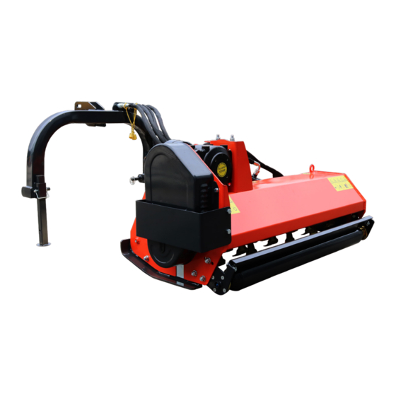
- Page 1 OFFSET BOOM MOWER BE-AGLXXXF OPERATIONS & PARTS MANUAL FOR MODELS: • BE-AGL125F • BE-AGL145F • BE-AGL165F PURCHASE DATE MODEL NO. SERIAL NUMBER DEALER...
- Page 2 TABLE OF CONTENTS General Information & Safety Set Up Transport & Storage Maintenance Instructions Exploded View & Parts Breakdown...
- Page 3 GENERAL INFORMATION INTRODUCTION: The AG Flails are primarily designed to mow grass, weeds and light brush. The mowers are assembled for operation with 1000 RPM tractor input only (rated PTO up to 45 HP), and supplied standard with Cat. I lift pins for tractor attachment. The mowers can fit Cat.
- Page 4 BE-AGLxxxF USER MANUAL...
- Page 5 ALLOWED USE: AG flail mowers, as described in this instruction and maintenance booklet, have been specifically designed to mow grass, weeds, and light brush up to 1” diameter. Any other use jeopardizes the operator’s safety and the machine integrity. IMPROPER USE: The mower was designed to mow grass, weeds, and light brush only.
- Page 6 GENERAL SAFETY RULES ALWAYS CONSIDER THE FEATURES OF THE AREA WHERE WORK IS TAKING PLACE: When the equipment is running, it is forbidden to stand within the field of action of the shredder or of the other accessories of which it is provided with. PREPARE THE WORK: •...
- Page 7 SET UP ATTACHMENT TO THE TRACTOR Before operating the mower, carefully read this Operator’s Manual, completely understand the safety instructions, and know how to operate both the tractor and the PTO shaft correctly, carefully reading the instruction manuals of the tractor and PTO shaft manufacturers. All AG flail mowers have been manufactured to be attached to any tractor provided with hydraulic and universal 3-point hitch.
- Page 8 DRIVELINE ATTACHMENT Before assembling the PTO shaft, check that its RPM and direction of rotation match those of the tractor. Moreover, carefully read the instruction manuals of the PTO shaft and the tractor manufacturers. Before starting work, make sure all safety shields are in place. Check in particular that the safety guards cover the PTO shaft throughout its extension.
- Page 9 6. Measure the clearance between the bottom of the extended blades and the ground. • Minimum 50mm • Note: in rough or lumpy paddocks the clearance needs to be increased to ensure that the blades don’t impact the ground in operation. 7.
- Page 10 TRANSPORT & STORAGE WORKING SPEED The working speed depends on quality, diameter and height of the material to be cut; for efficient mower performance it must be between 2 and 5 MPH. The power takeoff speed must be 1000 RPM maximum. Operate the mower at its full rated PTO speed to maintain blade speed for a clean cut.
- Page 11 MAINTENANCE Maintenance is a fundamental operation to extend the life and performance of any agricultural vehicle; taking care of the machine grants you not only proper efficiency and execution, but also a longer life of all the equipment and greater safety of the workplace. The operating times indicated in this manual have just an informative character and refer to normal conditions of use;...
- Page 12 8HRS / DAILY 50HRS / WEEKLY ANNUALLY Lubricate PTO Shaft Lubricate Caster Wheels Lubricate Blade Spindle Check Gear Box Oil Level Clean Machine Lubricate and Clean PTO Shaft Cover PTO SHAFT MAINTENANCE The PTO shaft is designed to telescope to allow for dimensional changes as the machine goes through its operating range.
- Page 13 EXPLODED VIEW & PARTS LISTS SYSTEM NO. PART NO. DESCRIPTION 503010763 DIN985-M12 Thin nut 506010057 GB97.1-12 Flat gasket 509010008 GB1152-M8X1 Oil cup 810240078 EFAGL165A-1200-00 Roller hanging board (L) 501011126 GB5783-M12X30 Screw bolt 511040007 EF100.00.012 UC205 bearing 501011888 GB5786-M14X1.5X40 Screw bolt 506010058 GB97.1-14 Flat gasket...
- Page 14 SYSTEM NO. PART NO. DESCRIPTION Sliding rail 2 810240086 EFAGL165A-1600-00 700920111 EF100.00.122B Board or chain 700920107 EF100.00.121 Board or chain 506010056 GB97.1-10 Flat gasket 700920108 EF100.00.122 Wide board or chain 700920109 EF100.00.122A Wide board or chain (L) 20-1 810420010 EFAGL105A-0200-00 (L=1086) Rod for board (105) 20-2 810280007 EFAGL125A-0200-00 (L=1274) Rod for board (125)
- Page 15 SYSTEM NO. PART NO. DESCRIPTION Screw bolt 501011131 GB5783-M12X55 506030037 Spring washer GB93-12 506010057 Flat gasket GB97.1-12 503010047 Hex nut GB6170-M12 810240082 Gear box pull rod EFAGL165A-1400-00 810240065 Gear box seat EFAGL165A-0500-00 801240040 (EFGC884) Gear box XH50.300Z.02W 802710038 EFAGL125.014 Tensioning plate 501011126 Screw bolt GB5783-M12X30...
- Page 16 SYSTEM NO. PART NO. DESCRIPTION 501011126 Screw bolt GB5783-M12X30 710340013 EFAGL165C-0000-06 Tensioning wheel hanging plate 503010763 DIN985-M12 Thin nut 503010740 DIN985-M16X1.5 Thin nut 515010005 REACH04-33X60 Power lock 701160007 EFG120.106A Big belt pulley (3 grooves) 503010046 GB6170-M10 Hex nut 506030036 GB93-10 Spring washer 506010056 GB97.1-10...
- Page 17 SYSTEM NO. PART NO. DESCRIPTION 501011127 GB5783-M12X35 Screw bolt 506030037 GB93-12 Spring washer 701520006 EFG120.168 Oil nipple 701520010 EFG120.169 Paper pad 511040032 UC207 Bearing 801140006 EFG100.013 (L=1003) Blade shaft (105) 801160021 EFG120.013 (L=1203) Blade shaft (125) 801180006 EFG140.013 (L=1403) Blade shaft (145) 801200006 EFG160.013 (L=1603) Blade shaft (165)
- Page 18 BE-AGLxxxF USER MANUAL...
- Page 19 SYSTEM NO. PART NO. DESCRIPTION 802710100 EFAGL125.030 (L=400) Support leg 703140001 MFP120.00.101 Seal cap 800920101 EF100.00.111A Square cotter 802710045 EFAGL125.017 Rear swing arm 511050221 SF-2-30X34X30 Self-lubricating bear-ing 509010009 GB1152-M10X1 Oil cup 501011098 GB5783-M8X16 Screw bolt 810240073 EFAGL165A-1000-00 Side-sway cylinder 810420012 EFAGL105A-0300-00 (105) Side-sway cyl-inder 705190066...
- Page 20 SYSTEM NO. PART NO. DESCRIPTION 703820055 QUICK-COUPLING-G1/2-G G1/2 pin end 810250003 EFAGL165B-0200-00 Pipeline 810250005 EFAGL165B-0400-00 Pipeline 810250004 EFAGL165B-0300-00 Pipeline BE-AGLxxxF USER MANUAL...
- Page 21 SYSTEM NO. PART NO. DESCRIPTION 810340023 EFAGL165C-0301-00 Tensioning wheel hanging frame 506060183 GB893.1-62 Circlip 511021549 GB276-6305-2RS 2RS Deep groove ball bearing 710340022 EFAGL165C-0300-01 Tensioning wheel 506060310 GB894.1-25 Circlip BE-AGLxxxF USER MANUAL...
- Page 22 B RA B E R EQ .CO M WGSALES@BRABEREQ.COM PHONE: 604-850-7770 FAX: 604-850-7774 TOLL FREE PHONE: 1-877-588-3311 TOLL FREE FAX: 1-800-665-7334 BE-AGLxxxF USER MANUAL...
Need help?
Do you have a question about the BE-AGL125F and is the answer not in the manual?
Questions and answers