
Summary of Contents for HORIBA STEC MT-52 Series
- Page 1 Digital Readout and Control Unit MT-52 Series Instructions (Ver.2.2) HORIBA PRECISION INSTRUMENTS (BEIJING) CO., LTD. CSMS5202...
-
Page 2: Table Of Contents
CONTENTS 1. INTRODUCTION......................1 2. SPECIFICATIONS......................2 3. DIMENSIONS & INSTALLATION................4 3.1 MT-52 Dimensions & Installation..............4 3.2 MT-52-2J/3J/4J Dimensions................7 4. PANEL INTRODUCTION..................12 4.1 Front Panel View....................12 4.2 Rear Panel View..................... 13 5. ELECTRICAL INTERFACE..................14 5.1 MFC Interface (D-sub 15/Female)..............14 5.2 COMM Interface (D-sub 9/Female).............. - Page 3 6.4 External Zero Adjustment................26 7. FACTORY DEFAULT SETTINGS................27 8. ATTENTIONS......................28 9. ORDERING GUIDE....................29 APPENDIX Ⅰ: RoHS.......................30...
-
Page 4: Introduction
1. INTRODUCTION MT-52 series flow display instruments can supply power, realize control operation, flow setting and flow display function for mass flow controller (MFC) or mass flow meter (MFM). -
Page 5: Specifications
2. SPECIFICATIONS Table 2-1. MT-52 Series Specifications MODELS MT-52 MT-52-2J MT-52-3J MT-52-4J ITEMS AC Power Supply 185~240VAC 50/60Hz Input Power Max. 19.8W 39.6W 59.4W 79.2W Channel Numbers =150mA =300mA =450mA =600mA DC Power +15V ± 5% Output -15V ± 5%... - Page 6 Continue to Table 2-1. MT-52 Series Specifications MODELS MT-52 MT-52-2J MT-52-3J MT-52-4J ITEMS Operating Temperature 0~50℃ Panel 96×96 483×110 (L×H) Dimensions (mm) Body 90×156×90 440×201×109 (L×W×H) Warm-up Time (min) Weight (Kg)
-
Page 7: Dimensions & Installation
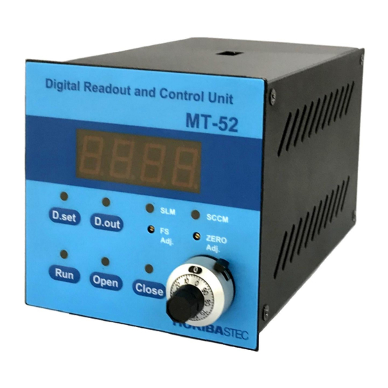
3. DIMENSIONS & INSTALLATION 3.1 MT-52 Dimensions & Installation 3.1.1 Dimensions Figure 3.1-1. MT-52 Exterior... - Page 8 Figure 3.1-2. MT-52 Dimensions (unit: mm)
- Page 9 3.1.2 Installation Fastener Fixing hole MT-52 Mounting plate Mounting Hole: 91×91mm Figure 3.1-3. MT-52 Installation Before Installation, fasteners are assembled as shown above. Then the MT-52 is inserted into the mounting hole of the mounting plate, and finally the fasteners are loaded into the fixing hole, and the screw should be tightened.
-
Page 10: Mt-52-2J/3J/4J Dimensions
3.2 MT-52-2J/3J/4J Dimensions Figure 3.2-1. MT-52-4J Exterior... - Page 11 Figure 3.2-2. MT-52-2J Dimensions (unit: mm)
- Page 12 Figure 3.2-3. MT-52-3J Dimensions (unit: mm)
- Page 13 Figure 3.2-4. MT-52-4J Dimensions (unit: mm)
- Page 14 Figure 3.2-5. MT-52-2J/3J/4J Dimensions (left elevation) (unit: mm) Note: The right elevation and the left elevation are mirror image.
-
Page 15: Panel Introduction
4. PANEL INTRODUCTION The panels and interfaces of MT-52 series flow display instruments are the same, take MT-52 as an example for explanation. 4.1 Front Panel View 1) Display window 2) “D.set” key & light (white) 3) “D.out” key & light (white) 4) “SLM”... -
Page 16: Rear Panel View
4.2 Rear Panel View ⑤ ① ⑥ ② ③ ④ ⑦ Table 4.2-1. Rear Panel Introduction Items Details AC220V input interface (for the sake of safety, "earth” AC_IN ① must be connected to the earth) COMM External control input/output interface ②... -
Page 17: Electrical Interface
5. ELECTRICAL INTERFACE 5.1 MFC Interface (D-sub 15/Female) Table 5.1-1. Pin Assignment of MFC Interface Details Details Chassis Ground External Zero Adj. ① Not Connected 9 & 10 Not Connected Signal Common -15VDC Power Supply SET Output -15VDC Power Supply Valve Override Not Connected Signal Common... -
Page 18: Comm Interface (D-Sub 9/Female)
5.2 COMM Interface (D-sub 9/Female) Table 5.2-1. Pin Assignment of COMM Interface Details Flow Signal Output (same as pin 7 of MFC interface ) +15VDC (only for external valve override, not for power supply) +5.00V Reference Voltage Signal Common External SET Input External Valve Override Input -15VDC (only for external valve override, not for power supply) Internal Valve Override Output... - Page 19 The “COMM interface” is an external controlling signals input/output interface. There are 3 external control methods that can be selected according to the actual situation as follows. First, you must turn the "INT / EXT" switch on the rear panel to "EXT" , which means "External Control".
- Page 20 (3) Connect the ground signal of the external signals to pin 4. Note: In this mode, the MFC which connected the instrument is controlled by the external “SET” signal. The “SET knob” on the front panel is not available. But the “Run”, “Open”, “Close”...
-
Page 21: Signal Interface
5.3 SIGNAL Interface The “OUT” pin of the SIGNAL interface is connected to pin 7 of the MFC interface and pin 1 of the COMM interface, which are both "Flow Signal". The interface is used for measuring the voltage of the "Flow Signal" to “Signal Common”. Note: 1. -
Page 22: Operating Instructions
6. OPERATING INSTRUCTIONS 6.1 Power On and Power Off MT-52 Power on: Connect AC220V power supply to the AC_IN interface Power off: Cut off the AC220V power supply of the AC_IN interface. MT-52-2/3/4J Power on: Connect AC220V power supply to the AC_IN interface, then turn on the red power switch on the front panel. - Page 23 6.2.1 Flow rate display / SET display Change The display window on the front panel can display “internal SET” signal as well as flow signal. The specific operations are as follows: Click “D.set” key, the “D.set” light will be on, and the window will display the current setting value of the “SET knob”.
- Page 24 6.2.3 Valve override operations Before performing the valve override operation, please confirm the valve override level according to the chapter “6.3.2 Valve Control Level Setting”. Internal valve override operation 1. “Valve Controlling” Click the “Run” key, then the “Run” green light will be on, and the “valve override”...
-
Page 25: Instrument Configuration
COMM interface. 6.3 Instrument Configuration MT-52 series flow instruments are equipped with two setting switches. The blue one named SW1 is the display F.S. change switch, and the red one named SW2 is the display configuration switch. See Table 6.3-1 and Table 6.3-2 for more details. - Page 26 Table 6.3-2 Gear & Function Cross-references of SW2 Items Details Gear Settings SLM light on the front panel is on 10 ON; 9 OFF Display Unit SCCM SCCM light on the front panel is on 9 ON; 10 OFF SLM and SCCM lights are not lit 9 &...
- Page 27 6.3.1 Display Settings Both the “internal SET” signal and the MFC flow signal are displayed through the display window on the front panel. 6.3.1.1 Display F.S. Setting When changing the display F.S., it is necessary to switch to the “D.set” state and rotate the “SET knob”...
- Page 28 6.3.1.2 Decimal Point Setting The 6, 7 & 8 gears of SW2 on the back panel are used to set the decimal point of the display value. For more details, see Table 6.3-2. 6.3.1.3 Unit Setting The 9 & 10 gears of SW2 on the back panel are used to set the display unit. For more details, see Table 6.3-2.
-
Page 29: External Zero Adjustment
6.4 External Zero Adjustment This function is only used for MFC or MFM with external zero adjustment ① Adjusting the “ZERO Adj.” potentiometer on the front panel can adjust the zero point of the connected MFC or MFM. If the connected MFC or MFM is replaced, the potentiometer needs to be adjusted again. -
Page 30: Factory Default Settings
7. FACTORY DEFAULT SETTINGS Taking our S500 AR111 as an example, If not specified, the initial settings of the MT-52 series display instruments are as follows: Factory default setting Switch Gear Meaning “Valve override” level 1 & 3 ON; “Valve cleaning” level: -15V (Mode A) 2 &... -
Page 31: Attentions
8. ATTENTIONS 1. The potentiometers inside the instrument have been adjusted before leaving the factory, and users should not adjust them at will. 2. If you connect the instrument with other MFCs, pay attention to whether the power supply capacity matches, and wiring and converting are correct. Pay attention to the level of MFC “valve override”... -
Page 32: Ordering Guide
3J: multi-display, 3 channels 4J: multi-display, 4 channels Note:You can specify the power-on valve control status of the MT-52 series display when ordering. In the unspecified state, the power-on status is “valve closing”, that is, the custom code is empty. -
Page 33: Appendix Ⅰ: Rohs
APPENDIX Ⅰ: RoHS 标记的意义 Meaning of Marking マークの意味 本标记适用在中华人民共和国销售电器电子产品,标记中央的数字表示环境保 护使用期限的年数。(不是表示产品质量保证期间。) 只要遵守这个产品有关的 安全和使用注意事项,从制造日开始算起在这个年限内,不会给环境污染、人 体和财产带来严重的影响。请不要随意废弃本电器电子产品。 This marking is applied to electric and electronic products sold in the People's Republic of China. The figure at the center of the marking indicates the environmental protection use period in years. (It does not indicate a product guarantee period.) It guarantees that the product will not cause environment pollution nor serious influence on human body and property within the period of the indicated years which is counted from the date of manufacture as far as the safety and usage... - Page 34 产品中有害物质的名称及含量 Name and amount of hazardous substance used in a product 有害物质 Hazardous substance 部件名称 六价铬 多溴联苯 多溴二苯醚 铅 汞 镉 Unit name Hexavalent Polybromo- Polybromo- Lead Mercury Cadmium chromium biphenyl diphenyl ether (Pb) (Hg) (Cd) (Cr (VI)) (PBB) (PBDE) Case ×...
- Page 35 HORIBA PRECISION INSTRUMENTS (BEIJING) CO., LTD. ADD.: No.40 Beiyuan Road Chaoyang District,Beijing China P.C.: 100012 TEL.: +86 10 84929402/9404/9453 FAX.: +86 10 84927216 E-MAIL: sales@horibaprecision.com WEBSITE: http://www.horibaprecision.com...
Need help?
Do you have a question about the MT-52 Series and is the answer not in the manual?
Questions and answers