Table of Contents
Advertisement
Available languages
Available languages
Quick Links
Advertisement
Table of Contents

Related Manuals for Velleman HAM06WS


Summary of Contents for Velleman HAM06WS
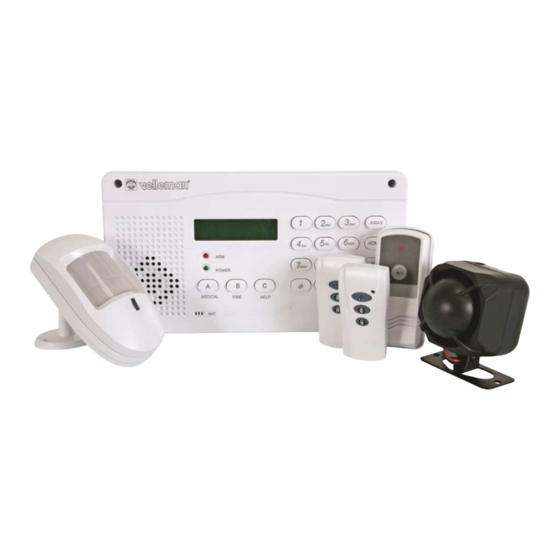
- Page 1 HAM06WS WIRELESS HOME ALARM DRAADLOOS ALARMSYSTEEM SYSTÈME D'ALARME SANS FIL SISTEMA DE ALARMA INALÁMBRICO DRAHTLOSES ALARMSYSTEM SISTEMA DE ALARME SEM FIOS USER MANUAL GEBRUIKERSHANDLEIDING NOTICE D’EMPLOI MANUAL DEL USUARIO BEDIENUNGSANLEITUNG MANUAL DO UTILIZADOR...
- Page 2 HAM06WS Rev. 04 18.04.2017 ©Velleman nv...
-
Page 3: Safety Instructions
If in doubt, contact your local waste disposal authorities. Thank you for buying the HAM06WS! Please read the manual thoroughly before bringing this device into service. If the device was damaged in transit, do not install or use it and contact your dealer. -
Page 4: Alarm Unit
HAM06WS • Connect the stand-by battery. • Screw the front plate onto the back plate and close the unit. 6. Connection • Telephone line: Connect an existing telephone line to RJ45 connector. Remark: If there is no telephone line connected, the central will display a message (“PATh TROUBLE”) and... - Page 5 HAM06WS d. Activating the alarm system There are two ways to activate the alarm system. 1. AWAY activation: The system reacts to all connected and programmed sensors. The message “ARM st” will be displayed and you will hear the vocal message “System armed”. Activate the system by pressing the AWAY button.
- Page 6 HAM06WS g. Menus Programming menu 1. Sys 2. Zone 3. Setup 4. Study Press a number to enter the corresponding submenu. Example: Press “1” to enter the “Sys” menu. “Sys” Menu The “Sys” menu has following submenus: 1. Level 2. Code 3.
- Page 7 HAM06WS Input arm zone Next, choose between 4 different alarm types for each zone. 1. Instant 2. delay 3. 24Hr 4. bypass Instant The alarm will immediately be triggered and the central unit will display a message. This mode is suited for window sensors.
- Page 8 HAM06WS Submenu 3 - Call 1. Tel 2. Dial 3. Vibrant ring This menu is used to program the telephone numbers to dial when the alarm is triggered. The number must consist of minimum 3 and maximum 13 digits. The message “PATh TROUBLE” will be displayed and a sound will be heard when the system has a faulty connection.
- Page 9 HAM06WS Select your zone (armzone 05 up to armzone 12). Zones 1 through 4 are reserved for wired sensors (terminal 5 ~ terminal 8 onto the PCB). Confirm with the # button. Following message will be displayed: be studying Next, activate the sensor. The central will emit a short beep and display the previous menu. The sensor has been assigned to its zone.
-
Page 10: Door Or Window Sensor
Current < 800mA Use this device with original accessories only. Velleman nv cannot be held responsible in the event of damage or injury resulted from (incorrect) use of this device. The information in this manual is subject to change without prior notice. - Page 11 – niet feilloos. De garantie geldt enkel voor het toestel zelf. Noch Velleman noch uw lokale verdeler kunnen verantwoordelijk gesteld worden voor welke schade of verlies dan ook voortvloeiend uit het falen van dit toestel of enig aangesloten randtoestel.
- Page 12 HAM06WS nodige aansluitkabels (kabels van de voedingsadapter, sensoren, sirene en eventuele telefoonaansluitingen) door de opening te halen. Schroef de achterplaat op de muur vast. • Sluit de nodige verbindingen aan op de voorziene aansluitklemmen (zie “§6. Aansluiting”). • Sluit de back-upbatterij aan.
- Page 13 HAM06WS met de afstandsbediening deactiveren (DISARM). Wanneer het alarm op scherp staat, bv. na het verstrijken van de tijdsvertraging, kan de centrale eenheid wel gebruikt worden. d. Activeren van het alarmsysteem Het alarmsysteem kan op 2 manieren scherp worden gesteld.
- Page 14 HAM06WS g. Menu’s Programmeringmenu 1. Sys 2. Zone 3. Setup 4. Study Druk steeds op de bijbehorende nummers om het aangegeven submenu weer te geven. Voorbeeld: Druk op toets “1” om in het menu “Sys” te komen. Menu “Sys” In het menu “Sys” kan men de volgende menu’s oproepen: 1.
- Page 15 HAM06WS Opmerking: De eerste 4 zones (arm zone1 - arm zone4) zijn toegewezen aan de sensoren die bekabeld zijn via de aansluitblokken 5 ~ 8. De draadloze sensoren (meegeleverd) zijn toegewezen aan zones 5 ~ 12. Input arm zone Vervolgens kan men voor de desbetreffende zone kiezen tussen 4 soorten alarm.
- Page 16 HAM06WS Set arm zone NO Submenu 3 - Call 1. Tel 2. Dial 3. Vibrant ring Hier kan men de nodige telefoonnummers invoeren die de centrale bij een alarmmelding moet oproepen. De invoer van de telefoonnummers moet steeds bestaan uit minstens 3 cijfers en maximaal 13 cijfers.
- Page 17 HAM06WS geheugen opgeslagen. Herhaal de vorige stappen om meerdere afstandsbedieningen in het systeem op te slaan. Submenu 2 – Arm zone Hier kan men maximaal 8 verschillende draadloze sensoren in het systeem opslaan en toekennen aan een bepaalde zone. Set arm zone NO.
-
Page 18: Technische Specificaties
< 800mA Gebruik dit toestel enkel met originele accessoires. Velleman nv is niet aansprakelijk voor schade of kwetsuren bij (verkeerd) gebruik van dit toestel. De informatie in deze handleiding kan te allen tijde worden gewijzigd zonder voorafgaande kennisgeving. -
Page 19: Notice D'emploi
– pas infaillible. La garantie est uniquement valable pour l’appareil. Ni Velleman, ni votre distributeur local ne sera responsable de dommages ou pertes à cause d’une faute de cet appareil ou de tout autre appareil périphérique connecté. - Page 20 HAM06WS dans le panneau arrière. • Effectuer le raccord nécessaire des bornes (voir « §6. Connexion »). • Raccorder l’alimentation de secours. • Refermer le boîtier. 6. Connexion • Ligne téléphonique : Raccorder une ligne téléphonique existante au connecteur RJ45. Remarque : L’unité centrale affichera un message (PATh TROUBLE) et ronflera s’il n’y a...
Need help?
Do you have a question about the HAM06WS and is the answer not in the manual?
Questions and answers