Advertisement
Quick Links
Advertisement

Summary of Contents for SMARTfit Mini Low Impact Portable
- Page 1 SMARTfit Mini Low Impact Portable Assembly Manual Version 1.4 www.smartfitinc.com...
-
Page 2: Table Of Contents
IMPORTANT SAFETY INSTRUCTIONS ....................... 2 Maintenance ............................3 Getting Started............................4 Unpackage the SMARTfit Mini Low Impact Portable ................5 Install the SMARTfit Mini Low Impact Portable ..................8 EU Declaration of Conformity (DoC) ..................... 22 Customer Service: 1-805-451-2488 x 112... -
Page 3: Important Safety Instructions
IMPORTANT SAFETY INSTRUCTIONS (READ ALL INSTRUCTIONS) CAUTIONS, WARNINGS and DANGERS • This is not a toy and is intended for use by or under the supervision of adults. • To reduce the risk of fire, replace only with a fuse of the same type and electrical rating. •... -
Page 4: Maintenance
Maintenance • Clean all surfaces with a water-based disinfectant, such as Windex Disinfectant. • Check all bolts and ensure they are tightened. • Check all mechanical parts for wear. • Check wiring for wear and fraying. Customer Service: 1-805-451-2488 x 112 www.smartfitinc.com... -
Page 5: Getting Started
• 37 categories consisting of hundreds of options that can be scaled to the ability level of players regardless of capability. • Adjustable touch sensitivity to suit the light touch of a hand or the weight of a medicine ball. • 18-month warranty and SMARTfit’s exclusive Platinum Service Plan. Extended warranty available. Customer Service If you need assistance, feel free to give our Customer Service a call at 1-805-256-0278, between the hours of 8:00 a.m. -
Page 6: Unpackage The Smartfit Mini Low Impact Portable
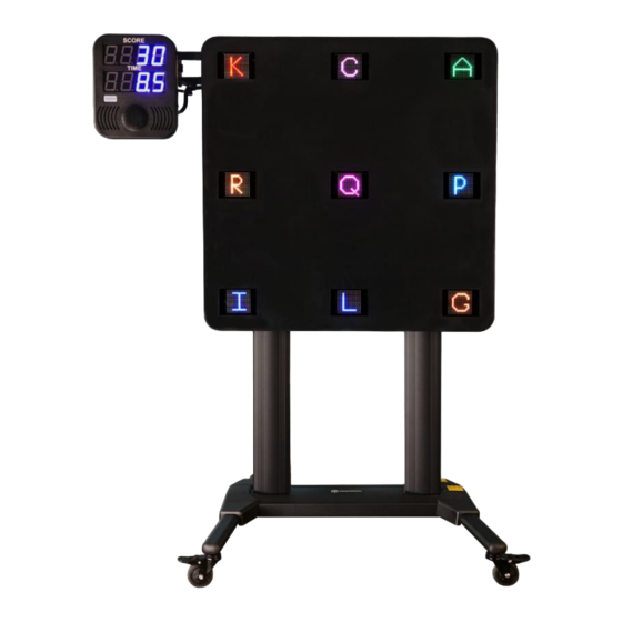
Unpackage the SMARTfit Mini Low Impact Portable Layout all received packages near an open area. Inspect all boxes before opening them. Photograph any damage. Now unpack the first box. This box contains the Low Impact Mini Panel. Lay it down safely in the packaging material so that it cannot damage the floor. - Page 7 This is the wheelbase that will attach to the panel. This is the SMARTfit Controller. This is the Controller Backplate with an Attachment Arm. The attachment arm will connect to the side of the panel and the Controller will attach to the backplate.
- Page 8 Yellow and blue pool noodles are used for striking the targets. Hurdles are included to enhance motor coordination during SMARTfit training sessions. Drumsticks are included to help frail clients strike each target. Sample QR/NFC wristbands for easy log in by clients. Client can scan wrist band after initial client account has been created.
-
Page 9: Install The Smartfit Mini Low Impact Portable
Install the SMARTfit Mini Low Impact Portable Turn over the panel so that the targets are facing down toward the floor or a table. The panel weighs 70 lbs, so two people are required to handle it. Now you are ready to attach the wheelbase to the panel. - Page 10 For this next step we made sure to set the panel face down on a table so that it was easier for us to attach the wheelbase. First, unravel the wires at the end of each post so that they can be fed through the wheelbase in the next step.
- Page 11 Secure the wheelbase onto the panel using the 4 screws we removed the nuts and washers from earlier. Reattach the washer and nut to each screw and secure it using the 10- millimeter socket and ratchet. There are two power supplies on the bottom of the wheelbase.
- Page 12 The final wire connected to the keypad can be brought over the back edge of the wheelbase. This is the same wire that we did not thread through the wheelbase. Plug this wire into the bottom of the power supply controlling the actuators.
- Page 13 To move the system around, unlock all 4 wheels by disabling the breaks. You can re-enable them at any time. There are a total of two wires that need to be plugged into the power outlet attached to the back end of the wheelbase.
- Page 14 The keypad will be taped nearby and wrapped in plastic. Align the screw holes on the bracket and keypad. Secure the screws using a hex 3- millimeter screwdriver. Next, we will attach the Controller backplate. First, remove the two screws from the top of the left post.
- Page 15 Align the backplate with these screw holes and secure the backplate. See the photo to ensure that the Controller backplate is facing the correct direction. The Controller will be attached next. First, remove the knob at the back of the Controller. Customer Service: 1-805-451-2488 x 112 www.smartfitinc.com...
- Page 16 Align and attach the 3 hooks on the backplate to the 3 holes on the back of the Controller. Reattach the knob to secure the Controller onto the backplate. There are two wires that need to plug into the Controller to give the system power.
- Page 17 This wire will power the entire system. Remove the blue tape holding it down as well. Plug the power cord into the power supply attached to the back of the Controller backplate. Customer Service: 1-805-451-2488 x 112 www.smartfitinc.com...
- Page 18 Notice the shape of the target wire and plug it into the side of the Controller. Notice the shape of the power cord wire and plug it the controller, just above the target wire. There are 3 provided zip tie locations.
- Page 19 Tighten the zip ties in all 3 locations. Cut the end of each zip tie to make it look nice. Remove the plastic on all 9 targets. Plug the power cord into a wall outlet to give the system power. Turn the power switch on located on the side of the Controller.
- Page 20 Each target should light up along with the Controller. At this point, the keypad can be used to adjust the position of the panel in relation to the participant using SMARTfit. Customer Service: 1-805-451-2488 x 112 www.smartfitinc.com...
- Page 21 Lastly, we will test all the sensors to ensure the system is ready for use. First, open the SMARTfit app. It is likely that you’ll need to download it from the app sotre and create an account first before you can connect to the system.
- Page 22 Touch each sensor to ensure each target disappears when struck. If this is not the case, then please contact our customer service line at 805-256- 0278. You are now ready to use SMARTfit. Customer Service: 1-805-451-2488 x 112 www.smartfitinc.com...
-
Page 23: Eu Declaration Of Conformity (Doc)
Identification of Radio Equipment: Model Number: 3-56323 CPU 12V Object of the declaration: Product Name: SMARTfit Mini and SMARTfit Panel The object of the declaration described above is conformity with relevant Union harmonization legislation: RED Directive 2014/53/EU EN 60950-1:2006+A11:2009+A1:2010+A12:2011+A2:2013 EN 301489-3v2.1.1 andEN 301489-17 3.2.0... - Page 24 CE mark and issued the EU-type examination certificate; Controller: 99819-10-EURED This declaration of conformity is issued under sole responsibility of the manufacturer. Signed for and on behalf of: SMARTfit, Printed Name: Jim Manley Date: 5/14/18 Title/Function: Place:...
Need help?
Do you have a question about the Mini Low Impact Portable and is the answer not in the manual?
Questions and answers