Table of Contents
Advertisement
Quick Links
LA02303B
Bluetooth SMART (BLE) Module
Key features
Support Bluetooth v5.1 core specification, support 2Mbps LE and LE long Range
Embedded a 32-bit ARM Cortex-M4F with float-point unit, with clock up to 90MHz
Data Memory: 256KB internal ROM, 192KB internal RAM, 1MB internal Flash
Frequency of system crystal oscillator: 40MHz\32.768KHz
Power supply voltage: 2.0V~3.6V
Operating temperature: -40℃~100℃
Operating frequency: 2400~2483.5MHz
TX output power:8dBm (Typical)
BLE Receiving sensitivity:
-95dBm @1Mbps; -92dBm @2Mbps; -98dBm @500Kbps; -103dBm @125Kbps
Dimension: 16mm*23.7mm*2.5mm
Interface:
Vertical Mount (Plug-In)
6 PWMs (GPIOs), 1 Available UART, 1 ADC (GPIO), 1 debug UART
Horizontal (SMD)
6 PWMs (GPIOs), 1 Available UART, 3 ADCs (GPIOs), 1 debug UART, 1 GPIO
Built-in PCB trace antenna
Integrates the Afero Secure Connectivity Stack
Supports Afero Easy Onboarding
Supports Afero Secure Over the Air updates
www.leedarson.com ▏Better Life with Better IoT Innovation
Advertisement
Table of Contents

Summary of Contents for Leedarson LA02303B
- Page 1 6 PWMs (GPIOs), 1 Available UART, 3 ADCs (GPIOs), 1 debug UART, 1 GPIO Built-in PCB trace antenna Integrates the Afero Secure Connectivity Stack Supports Afero Easy Onboarding Supports Afero Secure Over the Air updates www.leedarson.com ▏Better Life with Better IoT Innovation...
-
Page 2: Table Of Contents
6.1 Handing Precaution ........................15 6.2 Soldering Recommendation ....................... 15 7 Package Information ..........................16 7.1 Tape and Reel ..........................16 7.2 Package and Weight ........................16 8 Declaration .............................. 16 www.leedarson.com ▏Better Life with Better IoT Innovation 1 / 20... - Page 3 TABLE OF CHART Figure 1.1 Module ............................3 Figure 1.2 Product Application ........................3 Figure 1.3 LA02303B Block Diagram ......................4 Figure 3.1 Module Pin Out .......................... 7 Figure 4.1 Antenna Area ........................... 10 Figure 4.2 Horizontal Mounting ........................ 10 Figure 4.3 Reference Examples for Horizontal Mounting ................
-
Page 4: Introduction
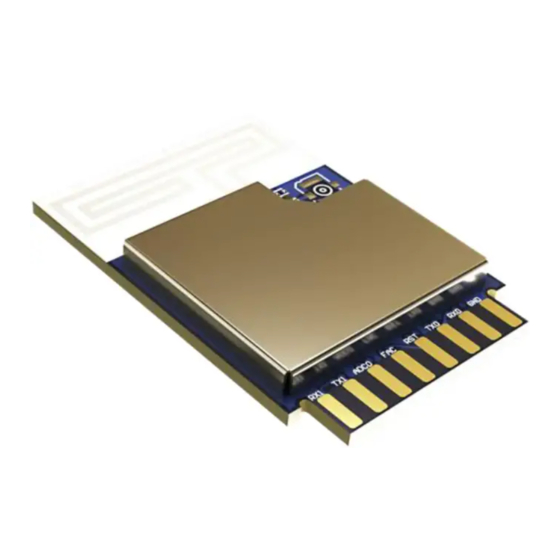
LA02303B BLE Module Specification 1 Introduction 1.1 Overview The LA02303B is a Leedarson-developed universal Bluetooth SMART (BLE) module. It uses the Realtek Inc. RTL8762DKF System in Package that integrates an embedded 1MB flash. Figure 1.1 Module It also integrates antenna on PCB which is designed for a variety of IOT products such as Door locker, Power Drivers, Sensors, Plugs, Lighting, Switches, etc. -
Page 5: Block Diagram
Crystal 40MHz Crystal 32.768KHz Figure 1.3 LA02303B Block Diagram 1.3 Ordering Information Table 1.1 Ordering Information Operating Product Protocol IC Solution. Dimension Antenna Temperature LA02303B RTL8762DKF -40 ~100℃ 16mm*23.7mm*2.5mm antenna www.leedarson.com ▏Better Life with Better IoT Innovation 4 / 20... -
Page 6: Electrical Characteristics
Supply current average 7.24 Note: 1. It refers in particular to the surface temperature on components of LA02303B when the module is working. If the surface temperature of components is above 100℃, the RF parameters will be worse; 2. It is measured when the module runs the RF test Firmware @25℃ ambient temperature, it is provided here for reference only. -
Page 7: Dc Specifications
Operating Frequency 2400 2483.5 Modulation GFSK Channel Number Channel Bandwidth Basic Transmitting Rate 1Mbps/2Mbps/500Kbps/125Kbps Frequency Offset -100 TX Power Receiving Sensitivity@1Mbps Receiving Sensitivity@2Mbps Receiving Sensitivity@500Kbps Receiving Sensitivity@125Kbps -103 Maximum Receiving Level www.leedarson.com ▏Better Life with Better IoT Innovation 6 / 20... -
Page 8: Antenna Specifications
Figure 3.1 Module Pin Out Table 3.1 Pin Definition The Pin (1-18) is used for Plug-in application. The Pin on Bottom layer used for SMD application. Pin 1 is adjacent to Pin 2. www.leedarson.com ▏Better Life with Better IoT Innovation 7 / 20... - Page 9 RTL8762D)/I2C data 44_P3_0 FACTORY_UART_TX data out Pull Up 22_P0_6 GPIO 8 Pull Down 43_P3_1 FACTORY_UART_RX data in Pull Up Ground of Module 2_P2_2 ADC0/IO6 Analog-to-Digital Converter 0/GPIO 6 Pull Down www.leedarson.com ▏Better Life with Better IoT Innovation 8 / 20...
-
Page 10: Trap Pins
If used as I2C SDA, an external pull up 17_P4_3 resistor is suggested to be reserved. If used as I2C SCL, an external pull up 18_P4_2 resistor is suggested to be reserved. www.leedarson.com ▏Better Life with Better IoT Innovation 9 / 20... -
Page 11: Design Guidelines
4 Design Guidelines 4.1 Power Supply The LA02303B requires a single nominal supply level of 3.3V. All the necessary decoupling and filtering components are included in the module. To secure the best RF performance, the power supply for the module is recommended to have the output current higher than 30mA and have the ripple voltage less than 100mV 4.2 Module Placement... - Page 12 Figure 4.5 Reference Examples for Vertical Mounting Regardless of which mounting method you choose, keep at least 1.5mm distance between module and plastic part, especially between the antenna and plastic housing. www.leedarson.com ▏Better Life with Better IoT Innovation 11 / 20...
-
Page 13: Package Specifications
Remark: due to the size and the shape of the application board could have impact on antenna patterns and efficiency, and different components make different coupling, different end products would have different antenna performance. 5 Package Specifications 5.1 Dimension Figure 5.1 Module Dimensions www.leedarson.com ▏Better Life with Better IoT Innovation 12 / 20... -
Page 14: Pcb Pads Information
It is suggested to add silk printing between the pads to avoid them welded together; www.leedarson.com ▏Better Life with Better IoT Innovation 13 / 20... -
Page 15: Smd Land Pattern Example
Figure 5.5 SMD Land Pattern Note: Antenna area refer to for antenna integration guidelines for optimal 4.2 Module Placement performance; The area marked by the R2 circle should be copper keep-out. www.leedarson.com ▏Better Life with Better IoT Innovation 14 / 20... -
Page 16: Production Guide
It is provided here for reference only. Note that the reflow times should not be more than 2 times. SMT TEMPERATURE SETTING Reflow Zone Soldering Time>30s Preheating Zone 120~225℃ 50~200s Cooling Zone Ramp-up Zone 0~50℃ Time(sec.) Figure 6.1 SMT Temperature Setting Curve www.leedarson.com ▏Better Life with Better IoT Innovation 15 / 20... -
Page 17: Package Information
This equipment has been tested and found to comply with the limits for a Class B digital device, pursuant to part 15 of the FCC rules. These limits are designed to provide reasonable protection www.leedarson.com ▏Better Life with Better IoT Innovation 16 / 20... - Page 18 This exterior label can use wording such as the following: “Contains FCC ID: 2AB2Q-LA02303B” any similar wording that expresses the same meaning may be used.
- Page 19 This exterior label can use wording such as the following: “Contains IC: 10256A-LA02303B” any similar wording that expresses the same meaning may be used. l'appareil hôte doit porter une étiquette donnant le numéro de certification du module d'Industrie Canada, précédé...
- Page 20 Host manufacturer is strongly recommended to confirm compliance with FCC/ISED requirements for the transmitter when the module is installed in the host. Must have on the host device a label showing Contains FCC ID: 2AB2Q-LA02303B or IC: 10256A- LA02303B Both FCC ID and IC ID are not to be placed on the host at the same time and only hosts going into the US can use the FCC ID and only hosts going into Canada can use the IC ID.
- Page 21 Doit avoir sur l'appareil hôte une étiquette indiquant Contient l'ID FCC ID: 2AB2Q-LA02303B ou IC : 10256A-LA02303B L'ID FCC et l'ID IC ne doivent pas être placés sur l'hôte en même temps et seuls les hôtes se rendant aux États-Unis peuvent utiliser l'ID FCC et seuls les hôtes se rendant au Canada peuvent utiliser l'ID IC.
Need help?
Do you have a question about the LA02303B and is the answer not in the manual?
Questions and answers