Advertisement
Table of Contents
- 1 Table of Contents
- 2 Product Introduction
- 3 Working Principle
- 4 Working Modes
- 5 Inspection
- 6 Installation
- 7 Outward Appearance and Wiring
- 8 Side and Front Panel
- 9 Battery Wiring
- 10 Parameter Settings
- 11 Product Care and Maintenance
- 12 Fault Codes
- 13 Fault Codes Troubleshooting
- 14 Buzzer Alerts
- 15 External Communication
- 16 General Installation Diagram
- Download this manual
ECO SW Series
User Manual
Ver. 3.0
ECO SW Series
WA R N IN G
IN V/C H R
AC
CAUTION:
High voltage. Avoid injury or dead by electrical shocks.
Before performing any electrical work turn OFF AC and
DC power supplies. Contact factory or local supplier for
technical service and support.
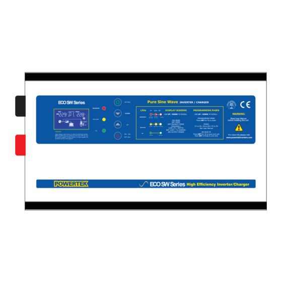
ECO SW Series 1.5 KW – 6 KW
Pure Sine Wave
INVERTER / CHARGER
SET(5s)
LEDs
DISPLAY SCREENS
On
blink Off
D OW N
USE
UP
/
DOWN
TO SCROLL
FAU LT /
LOW BAT /
WARNING
N OR M AL
OVL 115%
OVL 105%
INV MODE
BAT MODE
BAT PRIORITY MODE
U P
FREQUENCY
IN V ON
C H AR GIN G C H AR GED
INV/CHR
LOAD (% / WATTS)
BAT (VOLT / % CHARGE)
INV OUTPUT POWER
AC
ON (3s)
ON LIN E
OFF LIN E
OFF (5s)
ECO SW Series
PROGRAMMING PAGES
WARNING:
USE
UP
/
DOWN
TO SCROLL
PROGRAMMING MODE
Read User Manual
Press
SET
for 5s to enter
before installing this unit.
PAGES
P1 to P9 / PA to PN / F3 to F9
See User Manual
ON PAGE P0
Press
SET
for 3s to save and exit
For more info please visit:
Push
SET
2 times to exit only
www.powertekinverters.com
Advertisement
Table of Contents

Summary of Contents for PowerTek ECO SW Series
- Page 1 Before performing any electrical work turn OFF AC and ON LIN E OFF LIN E Push 2 times to exit only DC power supplies. Contact factory or local supplier for OFF (5s) www.powertekinverters.com technical service and support. ECO SW Series ECO SW Series 1.5 KW – 6 KW...
-
Page 2: Table Of Contents
CONTENTS 1. Product Introduction………………………………………………………………………………..1 1.1 Working Principle……………………………………………………………………………………..1 1.2 Working Modes………………………………………………………………………………………..2 2. Inspection…………………………………………………………………………………………………3 3. Installation………………………………………………………………………………………………..3 4. Outward appearance and wiring……………………………………………………………….5 4.1 Side and Front Panel………………………………………………………………………………….5 4.2 Battery Wiring……………………………………………………………………………………………6 5. Leds, Buttons and Display Description……………………………………………………….7 6. Parameter Settings…………………………………………………………………. ………………10 7. Product Care and Maintenance………………………………………………………………….17 8. -
Page 3: Product Introduction
1. Product introduction: The inverter is suitable for important equipment that requires backup power when the utility is unstable or absent. This product adopts high-precision DSP control chip, precise detection circuits, advanced control technology, modular design convenient for installation and maintenance and intelligent temperature-regulating fan for efficient heat dissipation to extend system’s life. -
Page 4: Working Modes
1.2. Introduction to working modes 01 Mains priority When the mains power is available, the Inverter supplies power to the load and charges the Battery. When the mains power is out of range, the battery will supply power to the load. You can set the mains power to charge the battery or not (Parameter PC set). -
Page 5: Inspection
not depending on the PC setting). 05 Solar priority mode (For inverters equipped with internal MPPT Charger) This mode is similar to Mode 03 (Battery priority Mode) but manages the internal MPPT Charger and the Inverter .When the battery voltage is normal, the inverter automatically turns on and the battery supply power to the load. -
Page 6: Installation
3. Installation recommendations: WARNING : Must be performed by a Certified Electrician 1. The inverter must have a minimum clearance of 30 cm away from any wall as shown in the next figure. Pick a place the Inverter on a well ventilated, free of humidity, flammables or corrosives gases. - Page 7 If connected to an outlet, the power outlet should be safely grounded. No matter if the inverter has input voltage or not, the inverter may have output voltage, turning off the inverter does not ensure that the internal parts don’t have power.
-
Page 8: Outward Appearance And Wiring
AC output (optional) input RS232 communication (optional) Neutral -Live -Ground/ Neutral -Live -Ground 1.5KW-3.5KW Series Pure Sine Wave ECO SW Series INVERTER / CHARGER S E T(5s) WA R N IN G LEDs DISPLAY SCREENS PROGRAMMING PAGES blink D OW N... -
Page 9: Battery Wiring
4.2 Battery Wiring 1. Battery wiring example: 1.1. 12V connection diagram: 1.2. 24V connection diagram: WARNING. Use the correct wires gauges according to the amount of Amps withdraw from the batteries and circulating through the wires. - Page 10 5. Leds indicators, Buttons and Display 1. Indicators and Push Buttons: Green light : On when the mains is present and the inverter operating Yellow light: Inverter working in battery mode indicator and mains charging indicator. When the inverter is working in Battery mode the light is solid ON, when the charger is charging the batteries this light flashes and when the charge is completed the light turns OFF.
- Page 11 Push Buttons: ON / OFF Button Turns the inverter ON : hold it for 5 seconds (buzzer will sound). Press again and hold 5 it for 5seconds to turn the inverter OFF UP /DOWN Buttons When the inverter is operating, press UP or DOWN to check parameters on the display: Inverter mode: Output Voltage Mains mode: battery capacity...
- Page 12 Load % display Load power display flash Overload display ( when icon flashes) Battery % display Battery voltage display Inverter total output power display Solar input with mains Solar input without mains...
-
Page 13: Parameter Settings
Solar input voltage (Volts) Solar input current (Amps) Setting Buttons: SET, UP/DOWN, ON-OFF Allows to enter in Programing or parameter setting mode 6. Programming Mode (PARAMETER SETTINGS): 1. When the inverter is working normally, press the SET button for 5S to enter to the setting menu (P0). - Page 14 P1: work mode setting: 01: Mains priority mode 02: Energy saving mode 03: Battery priority mode 04:Unnatended mode 05: Solar mode (option Internal MPPT Charger) P2: Battery type and charging voltage setting: SLD: sealed lead-acid battery, FLD: flooded lead battery, GEL: gel battery, LI: lithium battery, USE: user mode (default).
- Page 15 P5: Maximum mains charging current setting: 1500W (12VDC):45A 2500W and 3500W (24VDC):50A 3500W (24VDC): 50A P6: Buzzer sound setting: ON: Turn on the buzzer, OFF: Turn off the buzzer for: DC Mode, overvoltage, under voltage, overload, over temperature conditions except faults conditions) P7: Energy saving mode AC output setting: (10% default), can be adjusted up and down from 1.0-10%...
- Page 16 PA: Lower voltage setting on Battery Priority mode: 10.5V default, (single section: 10.5V, 10.6V, 10.7V, 10.8V, 10.9V, 11.0V, 11.1V, 11.2V, 11.3V, 11.5V) PB: Higher voltage setting on Battery Priority mode on battery priority mode, the battery voltage is restored and the inverter switches from city power to Inverting mod.
- Page 17 Pd: AC input lowest voltage setting: Default 80VAC, (70V, 75V, 80V, 85V, 90V) PE: AC input highest voltage setting: Default 135V, (130V, 132.5V, 135V, 137.5V, 140V, 142.5V, 145V) PF: AC input minimum frequency setting: Default 45Hz, (40Hz, 41Hz, 42Hz, 43Hz, 44Hz, 45Hz PH: AC input maximum frequency setting: Default 63Hz, (63Hz, 64Hz, 65Hz)
- Page 18 PN: battery voltage to restart the inverter on DC mode 13.8V default, (Single: 12.6V, 12.8V, 13.0V, 13.2V, 13.4V, 13.6V, 13.8V, 14.0V, 14.2V, 14.4V, can be set) F3: Generator mode setting: Default OFF (ON work with Gen. \ OFF doesn’t work with Gen. ) F4: Unattended mode battery lowest voltage to power off power the inverter’s MCU.
-
Page 19: Product Care And Maintenance
7.Product care and maintenance 7.1. This inverters Series is low maintenance. The standard battery type is valve-regulated lead-acid battery. When the inverter is connected to the mains, whether it is on or off, it may keep charging the battery depending on the working mode selected and provides overcharge and over discharge protection. -
Page 20: Fault Codes
8. Fault codes This icon will flash when there is a fault. Fault code display it will flash when there is a fault. 8.1. Fault codes and troubleshooting Cause Buzzer or indicator Fault cause Solution fault Battery low voltage Check the battery is broken or not 1 long 2 short (B-BB ) - Page 21 Intermittent beeping and Output for short Check if the output is light keeps circuit shortcircuited lighting overloaded Keep beeping, red light Output voltage is Check output voltage keep lighting and load overloaded Keep beeping, red light Temperature is too Check keep lighting high working...
-
Page 22: Buzzer Alerts
8.2. Buzzer alerts Buzzer sound: 1) Inverter: A beep sounds every 10 seconds. 2) When the battery voltage is low, one sound per second. 3) When the battery is high voltage: three sound every four seconds, one long and two shorts. - Page 26 Appendix1: Model ECO SW 1512 2512 2524 3524 4024 5024 6048 8048 10096 120096 Rated power 1500W 2500W 2500W 3500W 4000W 5000W 6000W 8000W 10000W 12000W Input Adjustable 145 min -275 Vac max Voltage Warning: The INPUT voltage must be supplied by a split phase transformer 120-240VAC, NOT Outpu Adjustable 85VAC min.- 145VAC max...
- Page 27 AC charging current ( MAX) 50A (MAX) can be set 5-10-20-30-40-50A 50A(MAX)can be set 5-10-20-30-40-50A 45A Max for 1500W Protection Overload, short circuit, battery high and low voltage, AC input high and low voltage protection Conversion method Interactive Overload capacity AC Mode: Overload 110-120%, the output will turn off after 30S.
-
Page 28: General Installation Diagram
GENERAL INSTALLATION DIAGRAM... - Page 30 WIRES SIZING The voltage drop calculations are based on the wire length indicated on top of the table (both positive and negative wires of the same length). WIRE LENGTH < 5 FEET 1524-2024 2524-3024 3624-4024 1512-1812 2512-3012 MODEL AWG 2 AWG 1/0 AWG 2/0 AWG 1/0...
- Page 31 AC Wire Gauge Recommended The following chart indicates recommended AC wire gauge for wire lengths up to 20 feet. MODEL 120V 220V 230V 120V 220V 230V INPUT BREAKER INVERTER 1500-12V 10 AWG 12 AWG 12 AWG 12 AWG 16 AWG 16 AWG INVERTER 1800-24V 10 AWG...
Need help?
Do you have a question about the ECO SW Series and is the answer not in the manual?
Questions and answers