Table of Contents
Advertisement
Quick Links
Industrial Machine Vision Controller
Release Date
Aug. 2020
Jul. 2021
®2020 Aplex Technology, Inc. All Rights Reserved. Published in Taiwan
Aplex Technology, Inc.
15F-1, No.186, Jian Yi Road, Zhonghe District, New Taipei City 235,Taiwan
Tel: 886-2-82262881 Fax: 886-2-82262883 E-mail:
URL:
www.aplex.com.tw
AVS-300
User Manual
aplex@aplex.com.tw
Revision
V1.0
V1.1
Advertisement
Table of Contents

Subscribe to Our Youtube Channel
Summary of Contents for Aplex AVS-300
- Page 1 Release Date Revision Aug. 2020 V1.0 Jul. 2021 V1.1 ®2020 Aplex Technology, Inc. All Rights Reserved. Published in Taiwan Aplex Technology, Inc. 15F-1, No.186, Jian Yi Road, Zhonghe District, New Taipei City 235,Taiwan Tel: 886-2-82262881 Fax: 886-2-82262883 E-mail: aplex@aplex.com.tw URL:...
-
Page 2: Revision History
Revision History Reversion Date Description 2020/08/10 Official Version 2021/07/06 Fix Pin definition AVS-300 Machine Vision User Manual... -
Page 3: Warning
Electric Shock Hazard – Do not operate the machine with its back cover removed. There are dangerous high voltages inside. AVS-300 Machine Vision User Manual... -
Page 4: Packing List
Packing List Accessories (as ticked) included in this package are: □ Adaptor □ Driver & manual CD disc □ Other.___________________(please specify) AVS-300 Machine Vision User Manual... -
Page 5: Safety Precautions
◆ Disconnect power when you change any hardware devices. For instance, when you connect a jumper or install any cards, a surge of power may damage the electronic components or the whole system. AVS-300 Machine Vision User Manual... -
Page 6: Table Of Contents
Warning…………………..........…………………………….……………………2 Packing List…………………………………….…………………………………………………....3 Safety Precautions…………………………………….…………….…..……………………....4 Chapter 1 Getting Started 1.1 Specifications…..………………...………………………………………………….6 1.2 Dimensions……..…………………..……………………………………………...7 1.3 Brief Description of AVS-300 …………….…..…………………….……8 Chapter 2 Hardware 2.1 Motherboard Introduction……………………..……………………..9 2.2 Specifications…………………………..…………..………………………………9 2.3 Motherboard Dimensions….……..…………..……………………………10 2.4 Jumpers and Connectors Location……….……………………………...11 2.5 Jumpers Setting and Connectors…………..………………………..……12... -
Page 7: Getting Started
Controller Intel Graphics 688/854 MHz(J1900) 1 x 1920 x 1200, by DB15 HDMI 1 x 1920 x 1200 Power 9~36V DC with 1x 3Pin power input connector Power Input 1 x 2Pin Power Switch Mechanical AVS-300 Machine Vision User Manual... -
Page 8: Dimensions
-40~85 °C Storage Humidity 10 to 90% @ 40 °C , non-condensing Certification CE / FCC Class A Operating System Microsoft® Win10 IoT, Windows 7 (32/64 bit) Support 1.2 Dimensions Figure 1.1: Dimension of AVS-300 AVS-300 Machine Vision User Manual... -
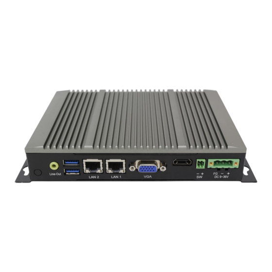
Page 9: Brief Description Of Avs-300
SIM slot for storage use, and 9~36V DC wide-ranging power input. AVS-300 has 1x mPCIE slot for expansion and it is plating titanium gray aluminum heatsink and black steel chassis designed. AVS-300 can be wall mounted, and it works well with our other products and they can provide an absolute easy way to perform control maintenance. -
Page 10: Chapter 2 Hardware
Chapter 2 Hardware 2.1 Motherboard Introduction SBC-7821 provides Intel Celeron J1900 processor and works well with AVS-300, which provides abundant peripheral interfaces to meet the needs of different customers. Also, SBC-7821 features various COM ports and GPIO choices. To satisfy the special needs of high-end customers, SBC-7821 is designed with 120-pin PCIe x 16 socket extension interface. -
Page 11: Motherboard Dimensions
Infineon’s Trusted Platform Module(TPM2.0, option) Operating: -20℃ to 70℃ Temperature Storage: -40℃ to 85℃ Humidity 10% - 90%, non-condensing, operating Meet CE/FCC Part15 class A EMI/EMS RoHS 2.3 Motherboard Dimension (SBC-7821) (Unit: mm) Figure 2.1: Motherboard SBC-7821 Dimensions AVS-300 Machine Vision User Manual... -
Page 12: Jumpers And Connectors Location
2.4 Jumpers and Connectors Location Figure 2.2: Jumpers and Connectors Location- Board Top Figure 2.3: Jumpers and Connectors Location- Board Bottom AVS-300 Machine Vision User Manual... -
Page 13: Jumpers Setting And Connectors
Output power of cooling fan must be limited under 5W. 4. DDR3: (SO-DIMM 204Pin socket), DDR3L memory socket, the socket is located at the top of the board and supports 204Pin 1.35V DDR3L 1333MHz FSB SO-DIMM memory module up to 8GB. AVS-300 Machine Vision User Manual... - Page 14 Power on the system again. d) When entering the POST screen, press the <DEL> key to enter CMOS Setup Utility to load optimal defaults. e) After the above operations, save changes and exit BIOS Setup. AVS-300 Machine Vision User Manual...
- Page 15 The two pins are disconnected under normal condition. You may short them temporarily to realize system startup & shutdown or awaken the system from sleep state. PWR LED: POWER LED status. 10. HDMI1: (HDMI 19P Connector), High Definition Multimedia Interface connector. AVS-300 Machine Vision User Manual...
- Page 16 AT24C02-DIP8,The EEPROM IC(U11) is the set of LVDS resolution. If you need other resolution settings, please upgrade U11 data. Model LVDS resolution 1280*1024 (Default) 800*480(option) SBC-7821F-XXX 800*600(option) 1024*768(option) 1920*1080(option) …… 14. INVT1(option): (2.0mm Pitch 1x6 wafer Pin Header), Backlight control connector for LVDS. AVS-300 Machine Vision User Manual...
- Page 17 Ground LVDS_VDD3 LVDS_VDD3 LB_D0_N LA_D0_N LB_D0_P LA_D0_P Ground Ground LB_D1_N LA_D1_N LA_D1_P LA_D1_P Ground Ground LB_D2_N LA_D2_N LB_D2_P LA_D2_P Ground Ground LB_CLK_N LA_CLK_N LB_CLK_P LA_CLK_P Ground Ground LVDS_DDC_DATA LVDS_DDC_CLK Ground Ground LB_D3_N LA_D3_N LB_D3_P LA_D3_P AVS-300 Machine Vision User Manual...
- Page 18 RXD (Received Data) TXD (Transmit Data) DTR (Data Terminal Ready) Ground DSR (Data Set Ready) RTS (Request To Send) CTS (Clear To Send) JP1 select Setting (RI/5V/12V) BIOS Setup: Advanced/NCT6106D Super IO Configuration/Serial Port 1 Configuration 【RS-232】 AVS-300 Machine Vision User Manual...
- Page 19 Signal Name 422_TX- 422_TX+ 422_RX+ 422_RX- Ground BIOS Setup: Advanced/NCT6106D Super IO Configuration/Serial Port 1 Configuration 【RS-422】 COM1: RS485 (option): Pin# Signal Name 485- 485+ Ground BIOS Setup: Advanced/NCT6106D Super IO Configuration/Serial Port 1 Configuration 【RS-485】 AVS-300 Machine Vision User Manual...
- Page 20 RXD (Received Data) TXD (Transmit Data) DTR (Data Terminal Ready) Ground DSR (Data Set Ready) RTS (Request To Send) CTS (Clear To Send) JP2 select Setting (RI/5V/12V) COM2: RS485 (option): Pin# Signal Name 485- 485+ AVS-300 Machine Vision User Manual...
- Page 21 COM3: RS232 (option): Pin# Signal Name DCD# (Data Carrier Detect) RXD (Received Data) TXD (Transmit Data) DTR (Data Terminal Ready) Ground DSR (Data Set Ready) RTS (Request To Send) CTS (Clear To Send) JP3 select Setting (RI/5V/12V) AVS-300 Machine Vision User Manual...
- Page 22 COM4 port is controlled by pins No.1~6 of JP4,select output Signal RI or 5V or 12V, For details, please refer to description of JP4 setting. COM4: RS232 (option): Pin# Signal Name DCD# (Data Carrier Detect) RXD (Received Data) AVS-300 Machine Vision User Manual...
- Page 23 (2.0mm Pitch 2x3 Pin Header),COM5 jumper setting, pin 1~6 are used to select signal out of pin 9 of COM5 port. JP5 Pin# Function Close 1-2 COM5 Pin9 RI (Ring Indicator) (default) Close 3-4 COM5 Pin9 = +5V/1A (option) Close 5-6 COM5 Pin9 = +12V/1A (option) AVS-300 Machine Vision User Manual...
- Page 24 RXD (Received Data) TXD (Transmit Data) DTR (Data Terminal Ready) Ground DSR (Data Set Ready) RTS (Request To Send) CTS (Clear To Send) JP5 select Setting (RI/5V/12V) COM5: RS485 (option): Pin# Signal Name 485- 485+ Ground AVS-300 Machine Vision User Manual...
- Page 25 (Type DB9M), Serial port, standard DB9 Male serial port is provided to make a direct connection to serial devices. COM6 port is controlled by pins No.1~6 of JP6,select output Signal RI or 5V or 12V, For details, please refer to description of JP6 setting. AVS-300 Machine Vision User Manual...
- Page 26 Ground DSR (Data Set Ready) RTS (Request To Send) CTS (Clear To Send) JP6 select Setting (RI/5V/12V) COM6: RS485 (option): Pin# Signal Name 485- 485+ Ground COM6: RS485 (option): Pin# Signal Name 485- 485+ Ground AVS-300 Machine Vision User Manual...
- Page 27 Any inconformity may cause system down and even hardware damages. Each USB Type A Receptacle (2 Ports) Current limited value is 2.0A. If the external USB device current exceeds 2.0A, please separate connectors into different Receptacle. AVS-300 Machine Vision User Manual...
- Page 28 Each USB Type A Receptacle (2 Ports) Current limited value is 2.0A. If the external USB device current exceeds 2.0A, please separate connectors into different Receptacle. 31. LAN1 (RJ45 Connector), Rear LAN port, one standard 10/100/1000M RJ-45 Ethernet port are provided. Used Intel I210AT chipset. AVS-300 Machine Vision User Manual...
- Page 29 Line in cable. MIC is the port for microphone input audio. Signal Name Pin# Pin# Signal Name +5V_AUD GND_AUD LINE-OUT-L LINE-OUT-R HPOUT_JD LINE_IN-JD LINE-IN-L LINE-IN-R MIC-IN-L MIC-IN-R GND_AUD MIC1_JD AVS-300 Machine Vision User Manual...
- Page 30 (50.95mmx30mm Socket 52Pin), mSATA socket, it is located at the top, it supports mini PCIe devices with LPCbus and SMbus and mSATA signal.B2 mSATA bus for flash disk signal. Function Support ● Mini SATA ● LPC bus ● SMbus ○ (co-lay, Option) USB2.0(USB3) AVS-300 Machine Vision User Manual...
- Page 31 Signal Name SIM_VCC Ground SIM_RST SIM_CD SIM_CLK SIM_IO SIM2(option): (MICRO SIM card slot),support SIM Card devices. 43. LED1/LED2 LED1 STATUS. Green LED for Motherboard Power status. LED2 STATUS. Green LED for Motherboard Standby Power Good status. AVS-300 Machine Vision User Manual...
- Page 32 Pin9-10: BUZZER, They are used to connect buzzer. Note: When connecting LEDs and buzzer, pay special attention to the signal polarity. Make sure that the connector pins have a one-to-one correspondence with chassis wiring, or it may cause boot up failure. AVS-300 Machine Vision User Manual...
-
Page 33: Chapter 3 Bios Setup
After CMOS discharge or BIOS flashing operation,Press [Delete] key to enter CMOS Setup. Version 2.17.1246. Copyright (C) 2021 American Megatrends, Inc. BIOS Date: 03/18/2021 16:10:47 Ver: 7821S004 Press 〈DEL〉or〈ESC〉to enter setup After optimizing and exiting CMOS Setup Press load default values continue 0085 AVS-300 Machine Vision User Manual... -
Page 34: Bios Setup Utility
Save & Exit BIOS Information Choose the system default Language BIOS Vendor American Megatrends Core Version 5.010 Compliancy UEFI 2.4; PI 1.3 Project Version 7821S 0.04 x64 Build Date and Time 03/18/2021 16:10:47 CPU Configuration Microcode Patch AVS-300 Machine Vision User Manual... - Page 35 Second : 0 to 59 System Date: Set the system date, the date format is: Day: Note that the ‘Day’ automatically changes when you set the date. Month: 01 to 12 Date: 01 to 31 Year: 1998 to 2099 AVS-300 Machine Vision User Manual...
-
Page 36: Advanced Settings
►System Component ►Network Stack Configuration ►CSM Configuration ►SDIO Computing ►USB Configuration ►Security Configuration ►Intel(R) I210 Gigabit Network Connection – 7C:CB:E2:… ►Intel(R) I210 Gigabit Network Connection – 7C:CB:E2:… Version 2.17.1246. Copyright (C) 2021 American Megatrends , Inc. AVS-300 Machine Vision User Manual... - Page 37 Serial Port 1 Configuration Serial port [Enabled] [Disabled] Device Settings IO=3F8h; IRQ=4; Change Settings [Auto] [IO=3F8h; IRQ=4] [IO=3F8h ;IRQ=3,4,5,6,7,9,10,11,12 ;] [IO=2F8h ;IRQ=3,4,5,6,7,9,10,11,12 ;] [IO=3E8h ;IRQ=3,4,5,6,7,9,10,11,12 ;] [IO=2E8h ;IRQ=3,4,5,6,7,9,10,11,12 ;] COM1 Mode Selection [RS-232] [RS-485] [RS-422] AVS-300 Machine Vision User Manual...
- Page 38 [IO=2F8h ;IRQ=3,4,5,6,7,9,10,11,12 ;] [IO=3E8h ;IRQ=3,4,5,6,7,9,10,11,12 ;] [IO=2E8h ;IRQ=3,4,5,6,7,9,10,11,12 ;] Serial Port 3 Configuration Serial port [Enabled] [Disabled] Device Settings IO=3E8h;IRQ=5; Change Settings [Auto] [IO=2F8h ;IRQ=3] [IO=3F8h ;IRQ=3,4,5,6,7,9,10,11,12 ;] [IO=3F8h ;IRQ=3,4,5,6,7,9,10,11,12 ;] [IO=3E8h ;IRQ=3,4,5,6,7,9,10,11,12 ;] [IO=2E8h ;IRQ=3,4,5,6,7,9,10,11,12 ;] AVS-300 Machine Vision User Manual...
- Page 39 Pc Health Status :+45 C System Temperature :N/A CPU Fan Speed :+0.864 V VCORE :+11.960V :+5.160V :+1.356V 1.35V 3.4.4 Intel(R) Smart Connect Technology ISCT Support [Enabled] [Disabled] 3.4.5 APM Configuration RTC Power On Function [Disabled] [Enabled] AVS-300 Machine Vision User Manual...
- Page 40 CPU Thermal Configuration [Enabled] [Disabled] CPU Speed 2001 MHz 64-bit Supported 3.4.7 PPM Configuration CPU c state Report [Enabled] [Disabled] SOix [Enabled] [Disabled] 3.4.8 Thermal Configuration Parameters Critical Trip Point [90C] Passive Trip Point [85C] AVS-300 Machine Vision User Manual...
- Page 41 [CORE offlining] Performance Control Setting [CORE offlining] DPPM [Enabled] 3.4.9 IDE Configuration Serial-ATA(SATA) [Enabled] [Disabled] SATA Test Mode [Enabled] [Disabled] SATA Speed Support [Gen2] [Gen1] SATA ODD Port [No ODD] [Port0 ODD] [Port1 ODD] SATA Mode AVS-300 Machine Vision User Manual...
- Page 42 3.4.10 Miscellaneous Configuration High Precision Timer [Enabled] [Disabled] Boot Timer with HPET Timer [Enabled] [Disabled] PCI Express Dynamic Clock Gating [Enabled] [Disabled] 3.4.11 LPSS & SCC Configuration LPSS & SCC Devices Mode [ACPI mode] [PCI mode] AVS-300 Machine Vision User Manual...
- Page 43 [Enabled] SCC SDIO Support [Enabled] [Disabled] SCC SD Card Support [Enabled] [Disabled] SDR25 Support for SDCard [Disabled] DDR50 Support for SDCard [Enabled] MIPI HSI Support [Disabled] [Enabled] LPSS Configuration LPSS DMA #1 Support [Disabled] [Enabled] AVS-300 Machine Vision User Manual...
- Page 44 LPSS I2C #6 Support [Disabled] [Enabled] LPSS I2C #7 Support [Disabled] [Enabled] I2C touch Device Address [AUTO] [0x4B] [0x4A] LPSS HSUART #1 Support [Disabled] [Enabled] LPSS HSUART #2 Support [Disabled] [Enabled] LPSS PWM #1 Support [Disabled] [Enabled] AVS-300 Machine Vision User Manual...
- Page 45 [AX STEPPING] [BX STEPPING] Witt Setting [Disabled] [Enabled] 3.4.13 Network Stack Configuration Network Stack [Disabled] [Enabled] 3.4.14 CSM Configuration Compatibility Support Module Configuration CSM Support [Disabled] [Enabled] CSM16 Module Version 07.76 GateA20 Active [Upon Request] [Always] AVS-300 Machine Vision User Manual...
- Page 46 [Do not launch] [UEFI] [Legacy] Video [Do not launch] [UEFI] [Legacy] Other PCI devices [UEFI] [Legacy] 3.4.15 SDIO Configuration SDIO Configuration [Auto] [DMA] [PIO] 3.4.16 USB Configuration USB Configuration USB Module Version 8.11.02 USB Devices: AVS-300 Machine Vision User Manual...
- Page 47 Device reset time-out [10 sec] [20 sec] [30 sec] [40 sec] Device power-up delay [Auto] [Manual] 3.4.17 Security Configuration Intel(R) TXE Configuration Intel(R) Anti-Theft Technology Configuration Intel(R) AT [Disabled] [Enabled] Intel(R) AT Platform PBA [Disabled] [Enabled] AVS-300 Machine Vision User Manual...
-
Page 48: Chipset Settings
F3:Optimized Defaults F4:Save and Exit ESC Exit Version 2.17.1246. Copyright (C) 2021 American Megatrends , Inc. 3.5.1 North Bridge ►Intel IGD Configuration GOP Configuration GOP Driver [Enabled] [Disabled] Intel IGD Configuration Integrated Graphics Device [Enabled] AVS-300 Machine Vision User Manual... - Page 49 [Enabled] [Disabled] GTT Size [2MB] IGD Thermal [Enabled] [Disabled] Spread Spectrum clock [Enabled] [Disabled] ISP Enable/Disable [Enabled] [Disabled] ISP PCI Device Selection [Enabled] [Disabled] Vcc,Vnn Configuration for Power state2: Vcc_Vnn Config for Power state2 [Enabled] AVS-300 Machine Vision User Manual...
- Page 50 [Enabled] [Disabled] Memory Information Total Memory 4096 MB(DDR3L) Memory Slot0 4096 MB(DDR3L) Memory Slot2 Not Present Max TOLUD [Dynamic] 3.5.2 South Bridge ►Azalia HD Audio Audio Configuration LPE Audio Support [Enabled] [Disabled] Audio Controller [Enabled] AVS-300 Machine Vision User Manual...
- Page 51 Azalia HDMI Codec [Enabled] [Disabled] HDMI Port B [Enabled] [Disabled] HDMI Port C [Enabled] [Disabled] ►USB Configuration USB OTG Support [Enabled] [Disabled] USB VBUS [On] [Off] XHCI Mode [Enabled] USB2 Link Power Management [Enabled] [Disabled] AVS-300 Machine Vision User Manual...
- Page 52 [Disabled] ►PCI Express Configuration PCI Express Port 0 [Enabled] [Disabled] Hot Plug [Enabled] [Disabled] Speed [Auto] Extra Bus Reserved Reserved Memory Reserved Memory Alignment Prefetchable Memory Prefetchable Memory Alignment Reserved I/O PCI Express Port 1 AVS-300 Machine Vision User Manual...
- Page 53 [Disabled] Speed [Auto] Extra Bus Reserved Reserved Memory Reserved Memory Alignment Prefetchable Memory Prefetchable Memory Alignment Reserved I/O PCI Express Port 3 [Enabled] [Disabled] Hot Plug [Enabled] [Disabled] Speed [Auto] Extra Bus Reserved Reserved Memory AVS-300 Machine Vision User Manual...
- Page 54 GPIO3 [High] GPIO4 Mode [Output] GPIO4 [High] GPIO5 Mode [Output] GPIO5 [High] GPIO6 Mode [Output] GPIO6 [High] GPIO7 Mode [Output] GPIO7 [High] GPIO8 Mode [Output] GPIO8 [High] Serial IRQ Mode [Quiet] [Continuous] Global SMI Lock AVS-300 Machine Vision User Manual...
-
Page 55: Security Settings
The password length must be F2: Previous Values F3:Optimized Defaults in the following range: F4:Save and Exit Minimum length ESC Exit Maximum length Administrator Password User Password ►Secure Boot menu Version 2.17.1246. Copyright (C) 2021 American Megatrends , Inc. AVS-300 Machine Vision User Manual... - Page 56 3.6.1 Administrator Password 3.6.2 User Password 3.6.3 Secure Boot menu System Mode Setup Secure Boot Not Active Secure Boot [Disabled] [Enabled] Secure Boot Mode [Custom] [Standard] Key Management AVS-300 Machine Vision User Manual...
-
Page 57: Boot Settings
F2: Previous Values F3:Optimized Defaults F4:Save and Exit ESC Exit Version 2.17.1246. Copyright (C) 2021 American Megatrends , Inc. Setup Prompt Timeout Bootup Numlock State [On] [off] Quiet Boot [Disabled] [Enabled] Fast Boot [Disabled] [Enabled] AVS-300 Machine Vision User Manual... - Page 58 VGA Support [Auto] [EFI Driver] USB Support [Disabled] [Full Initial] [Partial Initial] PS2 Devices Support [Disabled] [Enabled] Network Stack Driver Support [Disabled] [Enabled] Boot Option Priorities [UEFI:Built – in EFI … ] Boot Option #1 AVS-300 Machine Vision User Manual...
-
Page 59: Save & Exit Settings
Launch EFI Shell from filesystem device Reset System with ME disable ModeMEUD000 Version 2.17.1246. Copyright (C) 2021 American Megatrends , Inc. Save Changes and Exit Save & Exit Setup save Configuration and exit ? [Yes] [No] AVS-300 Machine Vision User Manual... - Page 60 Restore user Defaults Restore the User Defaults to all the setup options? [Yes] [No] Boot Override UEFI:Built – in EFI Shell Launch EFI Shell from filesystem device WARNING Not Found [ok] Reset System with ME disable ModelMEUD000 AVS-300 Machine Vision User Manual...
Need help?
Do you have a question about the AVS-300 and is the answer not in the manual?
Questions and answers