Table of Contents
Advertisement
Quick Links
ORDER NO. AD0001015C2
Amplifier
SE-HD510
Colour
(N).......................Gold Type
Areas
E..........................Spain and Sweden, etc..
EB.......................Great Britain.
EG.......................Europe.
EP.......................East Europe and Russia.
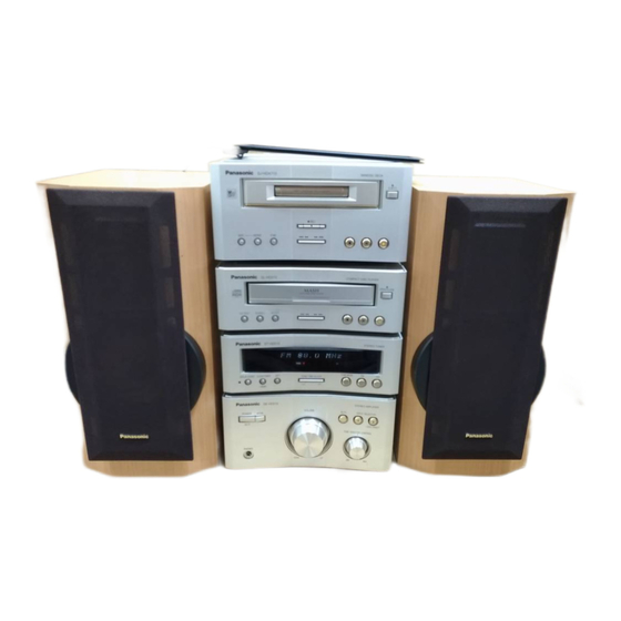
System: SC-HD510
Because of unique interconnecting cables, when a
compact requires service, send or bring in the entire
system.
SPECIFICATIONS
Specification
1
Advertisement
Table of Contents

Related Manuals for Matsushita Electric SE-HD510

Summary of Contents for Matsushita Electric SE-HD510
- Page 1 ORDER NO. AD0001015C2 Amplifier SE-HD510 Colour (N).......Gold Type Areas E......Spain and Sweden, etc.. EB.......Great Britain. EG.......Europe. EP.......East Europe and Russia. System: SC-HD510 Because of unique interconnecting cables, when a compact requires service, send or bring in the entire system. SPECIFICATIONS...
- Page 2 3.Total harmonic distortion is measured by the digital spectrum analyzer. System/SC-HD510: Tuner:ST-HD510, Compact Disc Player: SL-HD510, Amplifier: SE-HD510, Cassette Deck: RS-HDA710, Speakers: SB-HD510 (Made in MAES.) 2000 Matsushita Electric Industrial Co., Ltd. / / All rights reserved. Unauthorized copying and distribution is a violation of law.
-
Page 3: Before Repair And Adjustment
1. Accessories 2. Before Repair and Adjustment 1. Turn off the power supply. Using a 10 , 10W resistor, connect both ends of power supply capacitors (C102-105, 127) in order to discharge the voltage. 2. Before turning the power supply on, after completion of repair, slowly apply the primary voltage by using a power supply voltage controller to make sure that the consumed current at 50/60 Hz in NO SIGNAL mode should be shown below with respect to supply... -
Page 4: Operation Checks And Component Replacement Procedures
3. Press the STANDBY /ON button once again, supply the power. Note: When the protection circuitry functions, the unit will not operate unless the STANDBY button is first switched STANDBY and then ON again. 4. Caution for AC Main Lead 5. - Page 5 6.2. Checking for the operation P.C.B. - Follow the (Step 1) - (Step 3) of item 6.1. - Check the operation P.C.B. as shown below. / / / 6.3. Checking for the main P.C.B. - Follow the (Step 1) - (Step 3) of item 6.1.
- Page 6 - Check the main P.C.B. as shown below. 6.4. Replacement for the power IC - Follow the (Step 1) - (Step 3) of item 6.1. - Follow the (Step 1) - (Step 3) of item 6.3.
- Page 7 7. Power Source ON/OFF and Signal Check To operate this unit SE-HD510 normally, it is necessary for connecting with the unit ST-HD510. / When operating the unit SE-HD510, be sure to connect the unit ST-HD510 by connection cable. 1. Connect with the Tuner (ST-HD510). (As shown in Fig.
-
Page 8: Schematic Diagram Notes
4. Turn on the power of the Amplifier (SE-HD510). 5. Press INPUT SELECTOR to select the external source (EXT/MD) of the Amplifier (SE-HD510). 6. Input a sound signal to external input terminal of Tuner (ST- HD510), and confirm to be outputted from the speaker. (Both “High”... - Page 9 the chassis taken as standard. Therefore, there may exist some errors in the voltage values, depending on the internal impedance of the DC circuit tester. No mark: Power ON - Important safety notice: Components identified by mark have special characteristics important for safety.
- Page 10 (capacitors), low-noise (resistors), etc. are used. / When replacing any of components, be sure to use only manufacture's specified parts shown in the parts list. * The parenthesized indications in the Remarks columns specify the areas. / Parts without these indications can be used for all areas. * Remote Control Ass'y: Supply period for three years from terminal of production.
- Page 11 Ref. No. Part No. Part Name & Description Remarks RHD30007-S SCREW RKM0412-N CABINET XTBS3+10JFZ1 SCREW REX0962 FLAT CABLE(20P) RMZ0339 ZNR COVER XTB3+8JFZ SCREW RGN1777C-K NAME PLATE (E)(EG) RGN1777D-K NAME PLATE (EB) RGN1777E-K1 NAME PLATE (EP) RKA0114-K FOOT RKA0083-K CUSHION XTB3+5JFZ SCREW RGG0173A-N FRONT PANEL...
- Page 12 Ref. No. Part No. Part Name & Description Remarks C109 RCE1AKA470BG 10V 47U C110 ECEA1VKS470 35V 47U C111,12 ECKR1H103ZF5 50V 0.01U C113 ECBT1H103KB5 50V 0.01U C114 ECA1EAM101XB 25V 100U C115 ECA1EM222 25V 2200U C116 RCE1EM471BV 25V 470U C117 ECBT1H103KB5 50V 0.01U C118,19 ECA1EAK100XB 25V 10U...
- Page 13 Ref. No. Part No. Part Name & Description Remarks C533,34 ECBT1H102KB5 50V 1000P C535,36 ECBT1H473ZF5 50V 0.047U C537,38 ECA1EAM101XB 25V 100U C539,40 ECBT1C332KR5 16V 3300P C541,42 ECBT1H271KB5 50V 270P C543,44 ECBT1C222KR5 16V 2200P C545 ECBT1E223ZF 25V 0.022U C546 ECEA1HKS010 50V 1U C547-50 ECBT1H104ZF5 50V 0.1U...
- Page 14 Ref. No. Part No. Part Name & Description Remarks D307 MA165 DIODE D309,10 MA4120M DIODE D312,13 MTZJ7R5CTA DIODE D501 MA4150M DIODE D502 MA719TA DIODE D701-04 1N5402BF DIODE D705,06 RL1N4003N02 DIODE D707 MA4051M DIODE D708-10 MA165 DIODE D711-14 RL1N4003N02 DIODE D715 MA165 DIODE XBA2C06TB0...
- Page 15 Ref. No. Part No. Part Name & Description Remarks Q307,08 2SC3327A TRANSISTOR Q501 UN4115 TRANSISTOR Q502 2SC3311ATA TRANSISTOR Q503,04 2SC3327A TRANSISTOR Q505 2SC3311ATA TRANSISTOR Q508,09 2SC3311ATA TRANSISTOR Q510 2SA1309ATA TRANSISTOR Q511 2SC3311ATA TRANSISTOR Q512 2SA1309ATA TRANSISTOR Q701,02 2SC3311ATA TRANSISTOR R101 ERDS2FJ103 1/4W 10K R102...
- Page 16 Ref. No. Part No. Part Name & Description Remarks R511,12 ERDS2FJ103 1/4W 10K R513,14 ERDS2FJ563 1/4W 56K R515 ERDS2FJ334 1/4W 330K R516 ERDS1FJ331 1/2W 330 R517,18 ERDS2FJ2R2 1/4W 2.2 R519,20 ERDS2FJ563 1/4W 56K R521 ERDS2FJ684 1/4W 680K R522 ERDS2FJ473 1/4W 47K R523,24 ERDS2FJ272 1/4W 2.7K...
- Page 17 14. Cabinet Parts Location 15. Packaging...
- Page 18 Printed in Japan (H000104500KA/HH)
- Page 19 M5218AFPE3 RSN35H1 LM1876TF 2SB621AQRSTA 2SA1309ATA 2SC3311ATA UN4115TA 2SC3940AQSTA 2SD2374PQAU 2SD2144STA MA165TA MA4051MTA Cathode Cathode MA4062MTA MTZJ7R5CTA Anode Anode 1N5402BM21 SLR-325VC MA719TA MA4110MTA RL1N4003N02 MA4120MTA Cathode MA4150MTA Cathode Cathode Anode MA4160MTA Cathode MA4240MTA Anode Anode Anode...
-
Page 20: Power Supply Circuit
:POSITIVE VOLTAGE LINE POWER SUPPLY CIRCUIT :NEGATIVE VOLTAGE LINE :SOURCE SIGNAL LINE Q104 2SC3940AQSTA D120 RL101 REGULATOR C120 RL1N4003N02 25V100 31.4V R113 15.6V 3.9K R110 0.1V 3.9K 0.7V CN101 Lch IN Q103 A.GND 2SC3311ATA D102 MA165TA Rch IN RELAY DRIVE MUTE 5.6V POWER... -
Page 21: Main Circuit
:POSITIVE VOLTAGE LINE MAIN CIRCUIT :NEGATIVE VOLTAGE LINE :SOURCE SIGNAL LINE CN106 CP106 R116 2.5V 2.5V 1/4W 56 0.5V Q501 0.1V UN4115TA 0.6V MUTING CONT. D106 C504 R512 CN104 CP104 50V3.3 Q702 D105 2SC3311ATA R508 RELAY DRIVE D127 0.6V Q504 C503 R511 50V3.3... - Page 22 :POSITIVE VOLTAGE LINE :NEGATIVE VOLTAGE LINE :SOURCE SIGNAL LINE IC502 IC501 LM1876TF RSN35H1 POWER AMP(HIGH) POWER AMP(LOW) C546 50V1 R536 –B MUTE AC LATCH –Vcc +Vcc D502 MA719TA 15.6V 4.3V 14.8V 20.8V 0V R502 C506 C508 C507 C505 R542 2700P 1000P 1000P 2700P...
-
Page 23: Power Supply Pcb
POWER SUPPLY P.C.B. SPEAKER TERMINAL P.C.B. Q105 E C B C117 Q501 R114 B C E D118 B C E Q106 C501 CN716 C119 R702 C118 Q701 Q702 B C E R706 CN101 B C E R709 D104 R116 R534 R535 D103 Q511... - Page 24 OPERATION P.C.B. S303 POWER TRANSFORMER P.C.B. (INPUT SELECTOR –DVD DIRECT) C401 R401 W716 R402 S304 (INPUT SELECTOR (FINE VR401-1 TWEETER CONTROL) W713 VR401-2 5 6 7 R411 S305 R407 R408 (BLFS) D715 R412 W102 C311 C402 IC401 C422 C414 C312 RL702 C413 D309...
- Page 25 MAIN P.C.B. C553 C554 D710 D709 R701 R705 E502 CP106 CP104 CP105 4 3 2 1 5 4 3 2 1 5 4 3 2 1 L701 PT702 (POWER TRANSFORMER) JK701 Z701 AC IN 230V . . . [E,EG,EP] 230~240V . . . [EB] 50Hz D712 D714...
- Page 26 RSN35H1 IC501 POWER AMP(LOW) (13) SPEAKERS(HIGH) (14) (6 ) 2,15 SPEAKERS(LOW) D505, D503, Short (6 ) Q503 Muting Muting det. (Q504) Power Muting LM1876TF ON/OFF Q501 cont. -Vcc IC502 Bias POWER AMP(HIGH) +Vcc M5218AFPE3 IC401 FILTER AMP Q502,505, 508~512 Protector /over load det.
- Page 27 SPEAKER TERMINAL P.C.B. POWER SUPPLY P.C.B. SPEAKERS AC IN To TUNER 4 . . 1 W701 CP701 CN101 CP105 CN714 CP714 CN105 MAIN P.C.B. PT702 (Power transformer) CP104 CN104 W713 CP715 CN715 CN106 CN716 CP106 CN103 10 . PT701 (Power transformer) CN102 W716 POWER TRANSFORMER...
-
Page 29: Remote Control
Amplifier Standby indicator When the unit is connected to the AC mains supply, this indicator lights up in standby mode and goes out when the unit is turned on. Standby/on switch ( BLFS INPUT SELECTOR Press to switch the unit from on to standby mode or vice versa. MODE VOLUME In standby mode, the unit is still consuming a small amount of...
Need help?
Do you have a question about the SE-HD510 and is the answer not in the manual?
Questions and answers