Table of Contents
Advertisement
Quick Links
Document Part Number: 402197
Issue: 7.1
Date: January 2019
Teledyne Marine
International Avenue, ABZ Business Park,
Dyce, Aberdeen AB21 0BH UK
Tel: +44 (0)1224 772345
Email: tss_salesenquiries@teledyne.com
© 2019 Teledyne Ltd.
The information in this manual is subject to change without notice and does not represent a
commitment on the part of Teledyne Ltd. All drawings, technical content and the intellectual
property associated with this manual is property of Teledyne Ltd. No content should be copied or
distributed in any way without the express permission of the company.
HydroPACT 350
Subsea Cable Tracking System
User Manual
500272 - HydroPACT 350 110V a.c. 3000m
500277 - HydroPACT 350 230V a.c. 3000m
500320 - HydroPACT 350 110V a.c. 6000m
500321 - HydroPACT 350 230V a.c. 6000m
Advertisement
Table of Contents

Summary of Contents for Teledyne HydroPACT 350
- Page 1 Teledyne Ltd. All drawings, technical content and the intellectual property associated with this manual is property of Teledyne Ltd. No content should be copied or distributed in any way without the express permission of the company.
-
Page 2: Table Of Contents
2.3.5.1 Direct connection to the SEP ................2-21 2.3.5.2 Connection to the topside computer ..............2-21 3 Operating software ........................3-1 3.1 Initialisation ......................... 3-1 3.2 Initial Configuration ......................3-1 3.2.1 SEP type ........................3-2 3.2.2 Communication ports ....................3-2 DPN 402197 Issue 7.1 © Teledyne Limited... - Page 3 4.3.1 Data Logging ......................4-4 4.3.2 Replay Logged Data ....................4-4 4.4 After the Dive ........................4-5 4.5 Data Formats ........................4-6 4.5.1 External Logging Format .................... 4-6 4.5.1.1 Co-ordinates and Signals Format................ 4-6 © Teledyne Limited DPN 402197 Issue 7.1...
- Page 4 6.3.2 Communications Failure ..................... 6-5 6.3.3 Poor Tracking Performance ..................6-6 6.3.4 Altimeter Failure ......................6-7 6.4 Spares ..........................6-8 6.4.1 Coils ........................... 6-8 6.4.2 Subsea pods ......................6-8 6.4.3 Housings ........................6-8 DPN 402197 Issue 7.1 © Teledyne Limited...
- Page 5 B.2.4 Physical Installation ....................B-6 B.2.4.1 Search-coils ....................... B-6 B.2.4.2 Subsea Pods ..................... B-6 B.2.5 Electrical Connection ....................B-7 B.2.5.1 System Configuration ..................B-9 B.2.5.2 System Operation ....................B-9 B.2.6 Power Supply Requirement ..................B-10 © Teledyne Limited DPN 402197 Issue 7.1...
- Page 6 D.3 Fault Identification......................D-5 D.4 Battery Replacement ......................D-5 D.5 Maintenance ........................D-6 D.6 Specification ........................D-6 E Reference..........................E-1 E.1 Survey Details ........................E-2 E.2 System Configuration Details..................... E-2 F Index ............................F-1 DPN 402197 Issue 7.1 © Teledyne Limited...
-
Page 7: List Of Figures
List of Figures Figure 1-1: Components of the HydroPACT 350 system ............... 1-2 Figure 2-1: SEP mounting arrangement..................2-3 Figure 2-2: The coil array reference line..................2-4 Figure 2-3: Construction of the starboard coil triad ................ 2-5 Figure 2-4: Coil array mounting bar....................2-7 Figure 2-5: Coil separation reference marks .................. - Page 8 Figure A-1: Lines of magnetic flux ....................A-1 Figure A-2: Frequency ‘windows’ ....................A-2 Figure B-1: Sub-sea components of the Teledyne TSS 350 System ..........B-5 Figure B-2: Sub-sea components of the Teledyne TSS 440 System ..........B-6 Figure B-3: Electrical interconnection of subsea components............B-7 Figure C-1: Tone injection –...
- Page 9 Table 4-7: Internal logging format – Signals packet ..............4-11 Table 4-8: Altimeter output format – Benthos PSA 916..............4-12 Table 4-9: Altimeter output format – Teledyne TSS and Datasonics ........... 4-13 Table 4-10: Altimeter output format – Datasonics with pressure transducer ........ 4-13 Table 4-11: Altimeter output format –...
-
Page 10: Revision History
15/01/2008 Added 350 Coil Tester section to Appendix E. 14/06/2007 Updated default comms to RS232. 16/02/2006 Corporate rebranding changes and SDC9 updates. 19/12/2003 Revised for latest software. 25/07/2000 First release to cover SDC8/DeepView/440. DPN 402197 Issue 7.1 © Teledyne Limited... -
Page 11: Glossary
Vertical range to target. The distance measured by the 350 system along a line perpen- dicular to the coil surface, between the coil array and the closest point of the conductive target. © Teledyne Limited DPN 402197 Issue 7.1... -
Page 12: Introduction
1 – Introduction 1 Introduction The HydroPACT 350 system is a turnkey solution for performing accurate submarine surveys on tone- carrying cables. It operates in real time and provides accurate measurements at a rate that allows deployment on board faster ROVs. The measurement technology used by the system also allows it to operate out of water with no degradation in performance, range or accuracy. -
Page 13: Figure 1-1: Components Of The Hydropact 350 System
1 – Introduction ROV umbilical (user supplied) Communications Electrical Supply Figure 1-1: Components of the HydroPACT 350 system Table 1-1: Components of the HydroPACT 350 system Item Description Topside computer with DeepView installed Data cable for connection between the topside computerand the ROV umbilical Power and data cable (or ‘ROV Tail’) that connects the SEP to the ROV umbilical and power distribution... -
Page 14: Principle Of Operation
The presence of non-ferrous metallic objects in the search area ❐ 1.4 Warranty Please refer to your sales agreement with Teledyne Limited for information about the terms and duration of the warranty for this product. DPN 402197 Issue 7.1 © Teledyne Limited... -
Page 15: Product Support
Retain the original packaging to use when shipping this product between installa- tion sites or when returning it to Teledyne Limited or an authorised distributor for repair. The use of improper packaging for shipping any part of this equipment may invalidate the warranty. -
Page 16: Installation
2 – Installation 2 Installation To gain the best performance out of the HydroPACT 350 system you must take care when you install and connect it. This section includes the necessary information to help you identify suitable locations for the various components of the system, and install and prepare the systems for use. -
Page 17: Physical Installation
It is safe to mount the SEP in any orientation. Mount the SEP housing according to the following guidelines: Eliminate any possibility of snagging or damage to the SEP housing by installing it inside the ❐ outer limits of the ROV frame. © Teledyne Limited DPN 402197 Issue 7.1... -
Page 18: Coil Array
2-2, joins the centres of the port and the starboard lateral coils. Measurements of lateral offset are relative to the centre of the coil array and are positive if the ❐ target is to starboard and negative if it is to port. DPN 402197 Issue 7.1 © Teledyne Limited 2- 3... -
Page 19: Assembling The Coil Array
– for example to fit a new a sensing coil. To re-construct the coils after you have disassembled them you will need: A 3mm hexagonal key ❐ A 6mm hexagonal key ❐ © Teledyne Limited DPN 402197 Issue 7.1... -
Page 20: Figure 2-3: Construction Of The Starboard Coil Triad
6. Turn the fore-aft coil D so that it is to the right-hand side of the centre block with its 8-way con- nector pointing towards you as shown in Figure 2-3. Fit the coil to the groove so that the head DPN 402197 Issue 7.1 © Teledyne Limited 2- 5... -
Page 21: Mounting The Coil Array
ROV frame. The proximity of any large magnet such as that of an actuator. ❐ The presence of any conductive material between the coil triads that electri- ❐ cally shortens the coil separation distance. © Teledyne Limited DPN 402197 Issue 7.1... -
Page 22: Figure 2-4: Coil Array Mounting Bar
The bar has a receptacle groove 170mm long machined at the centre of one face. Make certain this receptacle is at the bottom when you install the bar onto the ROV. The receptacle is there to accept a Teledyne TSS altimeter if one is being used. Figure 2-4: Coil array mounting bar... -
Page 23: Figure 2-5: Coil Separation Reference Marks
1m and 1.76m). Make certain the coils are equally spaced about the ROV centre line. Tighten all the securing bolts of both clamping blocks evenly. Do not over tighten these bolts. Coil separation reference marks Figure 2-5: Coil separation reference marks © Teledyne Limited DPN 402197 Issue 7.1... -
Page 24: Figure 2-6: 350 Installation Drawing
2 – Installation Figure 2-6: 350 installation drawing DPN 402197 Issue 7.1 © Teledyne Limited 2- 9... -
Page 25: Altimeter Installation
With the altimeter mounted correctly, the 350 system will provide additional information and features: It will supply accurate depth of cover measurements with the target centred under the coils. ❐ 2-10 © Teledyne Limited DPN 402197 Issue 7.1... -
Page 26: Installation Checklist
This can be configured by setting links within the SEP and a switch on the SDC comms module. The SEP will need to be configured before mounting it onto the ROV. DPN 402197 Issue 7.1 © Teledyne Limited 2- 11... -
Page 27: Figure 2-8: System Interconnection Diagram
Altimeter cable. The SEP provides power to, and communicates with, the subsea altimeter through the sub- sea altimeter cable. Altimeter. Note that only certain types of altimeter can be connected directly to the SEP. 2-12 © Teledyne Limited DPN 402197 Issue 7.1... -
Page 28: Ground Connections
To avoid damage to the connectors, use only the lubricant oils mentioned above, or equivalent oils that the manufacturer approves specifically for use on deep-sea connectors and seals. When you apply the lubricant oil, use a very thin coating only. DPN 402197 Issue 7.1 © Teledyne Limited 2- 13... -
Page 29: Subsea Electronics Pod
SEP are through the power and communications cable (‘ROV tail’). Table 2-2 lists the pins of the connector on the power and communications cable, together with the relevant core 2-14 © Teledyne Limited DPN 402197 Issue 7.1... -
Page 30: Alternative Communication Methods
Re-fit all safety covers and ground connections to the 350 System before you re- connect the equipment to the mains electrical supply. Many components are susceptible to damage due to electrostatic discharge. You must take precautions against such damage: These precautions include the use DPN 402197 Issue 7.1 © Teledyne Limited 2- 15... - Page 31 2 – Installation of a grounded conductive mat and wrist-strap. Teledyne Limited will not accept responsibility for any damage caused by failure to take such precautionary measures. NOTE Alternative communications methods are only supported on systems with an SDC topside computer. Other configurations support RS232 only.
-
Page 32: Changing Communication Settings In The Sep
4. Use the 3mm hexagonal key to tighten the two M4 × 12mm screws alternately so that they lift the end-cap away from the SEP housing. DPN 402197 Issue 7.1 © Teledyne Limited 2- 17... -
Page 33: Figure 2-10: Link Location On The Sep Processor Board
Power Supply boards are located together on the other side. Change the communication links: Identify the Processor Board and locate the five links LK1 to LK5 as shown in Figure 2-10. Figure 2-10: Link location on the SEP processor board 2-18 © Teledyne Limited DPN 402197 Issue 7.1... -
Page 34: Table 2-3: Link Settings For Lk1 To Lk5
SEP housing is towards the right-hand end of the housing. You must insert the coil connector end-cap into the housing from the opposite end to the grounding lead. DPN 402197 Issue 7.1 © Teledyne Limited 2- 19... -
Page 35: Sensing Coils
Avoid introducing any sharp bends or other points of stress, and ensure that the cables are safe from potential damage from manipulators, thrust- ers or other equipment on the ROV. 2-20 © Teledyne Limited DPN 402197 Issue 7.1... -
Page 36: Subsea Altimeter
2.3.5.2 Connection to the topside computer Use this method to connect all other types of altimeter compatible for use with the HydroPACT 350 system. These altimeters use RS232 communications. To send their signals through the umbilical, you must add them to the ROV multiplex unit and extract them at the surface. -
Page 37: Table 2-4: Rs232 Connection To Com2
RS232 data from altime- Pin 2 (receive) RS232 data to altimeter Pin 3 (transmit). Necessary for use only with the OSEL Bathymetric System, where communications must be bi-directional. RS232 common Pin 5 (ground) 2-22 © Teledyne Limited DPN 402197 Issue 7.1... -
Page 38: Operating Software
The topside computer has DeepView pre-installed and configured to start automatically when it is powered on. NOTE The DeepView software application is used with all Teledyne TSS detection sys- tems. This chapter only covers functionality that applies to the 440 Pipe and Cable Survey System. -
Page 39: Sep Type
You should use this option even if you intend to use only one of the systems during the survey. 3.2.2 Communication ports NOTE During system configuration the only port that you have to specify is the communi- cation to the SEP. © Teledyne Limited DPN 402197 Issue 7.1... - Page 40 At this point the software will provide an analysis of the data status and will provide you with a summary screen of the findings that it has established. DPN 402197 Issue 7.1 © Teledyne Limited 3- 3...
-
Page 41: System Parameters
±1Hz or more in setting the frequency could cause the system to reject the tone. You may improve the performance of the System in the presence of background noise by using the Spectrum Analyser (see section 3.3.2.3) display to select a suitable tone frequency. © Teledyne Limited DPN 402197 Issue 7.1... -
Page 42: Tone Frequency Reminder Interval
Any target close to this null-response line will not produce an output from the vertical coil even when located very close to it. For the same reason, the threshold applies only to the fore-aft coils in the Forward Search mode. DPN 402197 Issue 7.1 © Teledyne Limited 3- 5... -
Page 43: Coil Separation
Print Configuration to send a copy of the System Configuration to the Windows Notepad application. You may edit the details and print them from this application. An example of the print configuration via Windows notepad. © Teledyne Limited DPN 402197 Issue 7.1... -
Page 44: Operating Deepview
Full analysis and post-processing of the raw data can be effective only if you retain a record of the 350 system configuration at the time of the survey. Configu- ration data is also critical for support requests to Teledyne Limited. Appendix E includes a suitable form for recording these details. -
Page 45: Menu Commands
Retain the hard copy prints with the survey records. Exit Use this command to exit the DeepView program and return to the Win- dows operating environment. © Teledyne Limited DPN 402197 Issue 7.1... - Page 46 [Ctrl + V] video overlay feature allows the topside computer to accept input from a video camera and to output the video image overlaid with the target co- ordinates and steering information. DPN 402197 Issue 7.1 © Teledyne Limited 3- 9...
- Page 47 This arrangement allows you to see the entire area of each window, although DeepView might resize the windows to fit the available area. This does not affect the Diagnostics Window or the Target Tracking Window. 3-10 © Teledyne Limited DPN 402197 Issue 7.1...
-
Page 48: View Menu
Figure 3-5: DeepView - Run Window DPN 402197 Issue 7.1 © Teledyne Limited 3- 11... - Page 49 Two data panels L and M show the received signal voltages. In Run mode, the voltages shown are measured simultaneously on the port vertical (PV), port lateral (PL), port forward (PF), starboard 3-12 © Teledyne Limited DPN 402197 Issue 7.1...
- Page 50 Dependent upon specific survey requirements, the Height Scale Display D on the Run Window can be modified. For example, if a small target is being tracked a reduced height scale may be required. This feature provides the user with control over the displayed height range. DPN 402197 Issue 7.1 © Teledyne Limited 3- 13...
-
Page 51: Forward Search Window
You cannot access this facility unless the system receives altitude information from an altimeter or unless you have configured the software to use a fixed coil height. Figure 3-6: DeepView - Forward Search Window 3-14 © Teledyne Limited DPN 402197 Issue 7.1... -
Page 52: Scope And Spectrum Analyser Window
Window. You must close the Run Window (or Forward Search Window) before you can access this command using either the menu or the toolbar button. DeepView can show signal data received using either ‘oscilloscope’ or ‘spectrum analyser’ displays. DPN 402197 Issue 7.1 © Teledyne Limited 3- 15... -
Page 53: Figure 3-7: Scope Window
The above screen shows an example of the 350 Spectrum Analyser Window with panels for six active channels. This shows the system tracking a 70Hz tone. The trace shows the expected peak at 70Hz and a peak at 50Hz (produced by the mains power frequency). 3-16 © Teledyne Limited DPN 402197 Issue 7.1... -
Page 54: System Errors Window
DeepView will delete the oldest message in the list to provide room for any new ones. Figure 3-9: System Errors Window The lines of text always have the format described in Table 3-2. DPN 402197 Issue 7.1 © Teledyne Limited 3- 17... -
Page 55: Terminal Window
The figure shows the Terminal Window displaying data packets from the 350 SEP in the client area. If you select the altimeter as the active serial device, the client area will show data packets from this device instead. Figure 3-10: Terminal Window 3-18 © Teledyne Limited DPN 402197 Issue 7.1... -
Page 56: Video Overlay Enable
SEP. To view data transmitted by an altimeter connected to an SDC serial communication port, use the Terminal Window described in section 3.3.2.3. DPN 402197 Issue 7.1 © Teledyne Limited 3- 19... -
Page 57: Figure 3-11: Altimeter Configuration
Sub-sea TSS* ❐ PSA 900** ❐ PSA 900 + depth** ❐ PSA 9000** ❐ PSA 916* ❐ Ulvertech Bathy ❐ Simrad UK90 ❐ OSEL Bathy ❐ SeaKing Bathy 704 ❐ Hyspec 305 ❐ 3-20 © Teledyne Limited DPN 402197 Issue 7.1... -
Page 58: Figure 3-12: Altimeter Test
The altimeter test allows you to see the serial data transmitted by an altimeter connected to the topside computer. The values shown will not have any meaning until the altimeter is immersed in water. Figure 3-12: Altimeter Test DPN 402197 Issue 7.1 © Teledyne Limited 3- 21... -
Page 59: External Data Logging
Certain parameters within DeepView will also be returned to their default states (see Table 3-6). Table 3-6: Factory System Defaults Parameter Default Value Tone Frequency Reminder Inter- 30 mins Video Overlay Parameters COM5, 9600, 8, n, 1 3-22 © Teledyne Limited DPN 402197 Issue 7.1... -
Page 60: Video Overlay Setup
The display overlaid on the external monitor from DeepView is shown in Figure 3-15. The video signal will be displayed behind this survey information where the black background is currently shown. DPN 402197 Issue 7.1 © Teledyne Limited 3- 23... -
Page 61: Toolbars
The normal condition is for the System Errors Window to be closed when you start to use DeepView. See for a full description of the Sys- section 3.3.2.3 tem Errors Window. 3-24 © Teledyne Limited DPN 402197 Issue 7.1... -
Page 62: Table 3-8: Run Window Toolbar
40 characters in length, to the file. The comments will appear in the status bar during replay of the file. The feature will not be available unless you have configured DeepView to generate an internal logging file. DPN 402197 Issue 7.1 © Teledyne Limited 3- 25... -
Page 63: Function Keys
350 System in a Dualtrack installation. 3.4 Replaying a Log File When you start to replay a log file an additional tool bar appears at the top of the run window. 3-26 © Teledyne Limited DPN 402197 Issue 7.1... -
Page 64: Quality Control
The two-digit identification number allows post-processing engineers to identify the quality control failure. See section 4.5.1 for details of the QC check code. The extremities of the Quality Control envelope are as follows: DPN 402197 Issue 7.1 © Teledyne Limited 3- 27... -
Page 65: Reinstall Deepview Procedure
3. In the Windows File Manager, select the folder C:\Program Files\TSS, and delete the subfolder DeepView for Windows. 4. Insert the software USB, and run the installer file DeepView_Install.exe (the exact name of this file may vary). 3-28 © Teledyne Limited DPN 402197 Issue 7.1... -
Page 66: Operating Procedure
350 system. By making this decision early in the planning process they can assign the correct equipment and personnel to the operation. Contact Teledyne Limited for advice if you are unsure whether the 350 system is suitable for use in a particular survey application. -
Page 67: Survey Requirements
This section describes a series of checks that you should perform on the 350 system before you deploy the ROV and start the survey. Perform these checks carefully, noting any safety issues as you do so: © Teledyne Limited DPN 402197 Issue 7.1... -
Page 68: During The Survey
Use Forward Search mode to locate a target that crosses the path of the ROV and then use the signal strength bars and the Run Window to steer along its course. Figure 4-1: Using the forward search mode 3. Perform the main survey: DPN 402197 Issue 7.1 © Teledyne Limited 4- 3... -
Page 69: Data Logging
For this reason, DeepView does not include a time field in the external data packets. See section 3.3.3.3 for a description of the external logging format. © Teledyne Limited DPN 402197 Issue 7.1... -
Page 70: After The Dive
5. Power-off the sub-sea installation. If you power-off the sub-sea installation before you close DeepView, the program will register a communications failure. DPN 402197 Issue 7.1 © Teledyne Limited 4- 5... -
Page 71: Data Formats
5. The vertical range to target (VRT) is the distance between the centre line of the coil array and the target. There are several conditions that will cause the field to contain question marks: © Teledyne Limited DPN 402197 Issue 7.1... -
Page 72: Table 4-2: Qc Check Code Meaning - Survey Mode
Table 4-2: QC check code meaning – Survey mode Check Meaning Code Target in range. SL and PL 50µV; LAT ±2m. Quality flag is RESET. Target in range. SL or PL <50µV; LAT ±2m. Quality flag is SET. DPN 402197 Issue 7.1 © Teledyne Limited 4- 7... -
Page 73: Forward Search Mode
3-2). There are several conditions that will cause the field to contain question marks: The target is out of range ❐ The 350 System cannot compute an accurate position for the target ❐ © Teledyne Limited DPN 402197 Issue 7.1... -
Page 74: Internal Logging Format
The values in the packet are rounded and it is possible that they will not precisely match those on the Run Window. Table 4-5: Internal logging format – Survey co-ordinates DPN 402197 Issue 7.1 © Teledyne Limited 4- 9... -
Page 75: Table 4-6: Internal Logging Format - Forward Search Mode
The values in the packet are rounded and it is possible that they will not precisely match those on the Forward Search Window. Table 4-6: Internal logging format – Forward search mode 4-10 © Teledyne Limited DPN 402197 Issue 7.1... -
Page 76: Table 4-7: Internal Logging Format - Signals Packet
The string is 34 characters long with individual field definitions as follows. DeepView logs all signal voltages in units of microvolts. Table 4-7: Internal logging format – Signals packet NOTE The Start character is a colon. ❐ DPN 402197 Issue 7.1 © Teledyne Limited 4- 11... -
Page 77: Altimeter Data Format
‘A1’ or packet ‘A2’, followed immediately by packet ‘B’. 4.6 Altimeter Data Format You may use certain types of altimeter manufactured by Teledyne TSS, Teledyne Benthos, Datasonics, Ulvertech, Simrad and OSEL with the HydroPACT 350 system. section 2.3.5.2 for instructions to connect one of these alternative types of altimeter to the topside computer. -
Page 78: Datasonics Psa 900 And Psa 9000
4.6.2 Datasonics PSA 900 and PSA 9000 The transmission formats for the Teledyne TSS altimeter, and the Datasonics PSA 900 and PSA 9000 are identical. They transmit data at 2400 baud using 7 data bits, 1 start bit, 1 mark bit and 1 stop bit. -
Page 79: Simrad Uk90
2. The contents of these output data fields are set externally and have no effect on operation of the HydroPACT 350 system. 4.6.5 OSEL Bathymetric System The OSEL Bathymetric system transmits data at 9600 baud using 8 data bits, 1 stop bit and no parity. -
Page 80: Tritech Seaking Bathy 704
DeepView transmits the interrogating character automatically when configured to use the OSEL altimeter. 4.6.6 Tritech SeaKing Bathy 704 The SeaKing Bathy system transmits data continuously using RS232 communications at 9600 baud. DPN 402197 Issue 7.1 © Teledyne Limited 4- 15... -
Page 81: Table 4-14: Tritech Seaking Bathy Format
For example, if the count were 162712, then: Altitude = ((162712 × 200ns) × 1475) 2 = 24.000 metres This is the true distance from the transducer face of the altimeter to the seabed. 4-16 © Teledyne Limited DPN 402197 Issue 7.1... -
Page 82: Operational Considerations
The following paragraphs describe the potential sources of error that might arise as a result of unskilled or inappropriate operation of the ROV. These include: The relative positions of the ROV and the target ❐ ROV trim and skew ❐ DPN 402197 Issue 7.1 © Teledyne Limited 5- 1... -
Page 83: Rov Position Over The Target
It is important also to recognise that, under the above conditions, these errors affect only the depth of cover measurements. Summary: Install the altimeter correctly at the centre of the coil array. ❐ Pay careful attention to the relative position of the ROV over the target. ❐ © Teledyne Limited DPN 402197 Issue 7.1... -
Page 84: The Effects Of Roll, Pitch And Skew
If there is a slight crosscurrent in the survey area, it may be possible to perform the survey only with a small angle of skew present. Under these circumstances, the system will continue to supply valid data DPN 402197 Issue 7.1 © Teledyne Limited 5- 3... -
Page 85: Slope
Make certain there is a negligible fore-aft offset distance between the coil array and the transducer face of the altimeter. Angles of slope less than half the beamwidth of the altimeter will not affect the measurements in this way. © Teledyne Limited DPN 402197 Issue 7.1... -
Page 86: Electrical Interference
Slow movements, such as those of the ROV manoeuvring, will have a negligible effect since the resulting induced voltages will be at a frequency below the pass-band of the 350 system. DPN 402197 Issue 7.1 © Teledyne Limited 5- 5... -
Page 87: Power-Carrying Cables
In very severe cases, the shorter return path might cause errors to appear in measurements made by the 350 system. In these conditions, the characteristics of the return path are uncertain, making it impossible to predict the magnitude of errors. © Teledyne Limited DPN 402197 Issue 7.1... -
Page 88: Curved Target Course
If your ROV has an automatic facility for maintaining altitude, you may use it. DPN 402197 Issue 7.1 © Teledyne Limited 5- 7... -
Page 89: Tracked Rov
You may install the 350 system on tracked ROVs. This type of ROV should allow you to set a fixed coil height. If you mount the system on an ROV of this type, locate the coils approximately one metre above the seabed. © Teledyne Limited DPN 402197 Issue 7.1... -
Page 90: Maintenance
6 – Maintenance 6 Maintenance CAUTION Teledyne Limited accepts no liability for field repairs. The warranty of spare parts may be affected if incorrectly fitted. If in doubt, contact Teledyne Limited. 6.1 System Description The 350 system comprises a search coil array, a subsea pod, the topside computer, an altimeter (optional) and associated cabling. -
Page 91: Coil Cable Continuity
8-way connectors on the cable. Labels identify the cable tails. 6.3 Fault Identification The remainder of this section includes advice and a series of flow charts to help you locate a fault in the sub-sea components of the 350 system. NOTE © Teledyne Limited DPN 402197 Issue 7.1... - Page 92 6 – Maintenance If your system fails, perform the following checks before you call Teledyne TSS engineers for assistance. 1. Check that you have installed the 350 system correctly according to the instructions in Chapter 2. Check that the configuration of the 350 system is correct. See section 3.2.3...
-
Page 93: Fault On A Single Channel
Swap out the coil on the faulty channel Is the channel Renew the faulty working? coil Swap out the SEP Is the channel Renew the faulty working? Contact Teledyne Figure 6-2: Single channel failure © Teledyne Limited DPN 402197 Issue 7.1... -
Page 94: Communications Failure
Power on the system Check the mains Contact Teledyne power supply 11 V ± 0% OK? source Look for 230V instead if your SEP operates from a 230V supply Figure 6-3: Communications failure DPN 402197 Issue 7.1 © Teledyne Limited 6- 5... -
Page 95: Poor Tracking Performance
All coils OK? channel Coil connections Connect coils correctly Use a different tone Is tone noisy? frequency System setup Reconfigure system correctly Coil separation Increase coil >1.4m? separation Contact Teledyne Figure 6-4: Poor tracking performance © Teledyne Limited DPN 402197 Issue 7.1... -
Page 96: Altimeter Failure
6 – Maintenance 6.3.4 Altimeter Failure This flow chart should help you to identify a fault with the Teledyne TSS ALT-250 altimeter connected directly to the SEP. If a fault develops when you use an alternative altimeter connected to COM2,... -
Page 97: Spares
6 – Maintenance 6.4 Spares NOTE Teledyne Limited has brought its spares strategy for detection systems into line with other product lines. 6.4.1 Coils TSS Part Number Description B933650 350 coil 6.4.2 Subsea pods TSS Part Number Description 490234/S 350 pod,110V a.c., 3,000m rated 490235/S 350 pod, 230V a.c., 3,000m rated... -
Page 98: Electronics
A.C. input cable, 3m B930477 Dualtrack cable, 2.5m 601824 ALT-250 altimeter cable, 3m B934985 350 pod cable harness set 6.4.9 Other TSS Part Number Description B934908 350 coil mounting kit B935028 Universal support kit DPN 402197 Issue 7.1 © Teledyne Limited 6- 9... -
Page 99: System Specifications
NOTE Teledyne Limited has made every effort to ensure that the specifications included are correct. However, in line with the Teledyne Limited policy of continual product development and improvement, Teledyne Limited reserves the right to change equipment specifications without notice. Refer to Teledyne Limited for advice if necessary. -
Page 100: Performance
7.2 Performance Figure 7-1 defines the vertical range measurement accuracy of the 350 system for the stated conditions of tone current – i.e. 30mA at 25Hz. Figure 7-1: Vertical range measurement accuracy DPN 402197 Issue 7.1 © Teledyne Limited 7- 2... -
Page 101: System Trials
❐ tudes and frequencies. Teledyne TSS conducted the tests using the central straight run of cable that spanned the diameter of the loop. This arrangement reduced any effect that the current return path around the outside of the loop may have had upon readings. -
Page 102: Results
Lateral offsets, vertical range, and errors are all listed in units of centimetres. ❐ ‘o/s’ signifies that the 350 system switched to one-sided calculations – to ❐ indicate which side the cable lay but not its offset distance. DPN 402197 Issue 7.1 © Teledyne Limited 7- 4... -
Page 103: Table 7-1: Vertical Measurement Errors
– you should not use them to correct measurements you have already taken. Table 7-1: Vertical measurement errors Lateral offset Vertical range -800 -600 -400 -300 -250 -220 -200 -180 -160 -140 -120 -100 -129 © Teledyne Limited DPN 402197 Issue 7.1... -
Page 104: Update Rate
Update rates available from independent seabed profiling systems may be different from the update rate you have set for the 350 system. If your ROV includes both these systems, you must allow for their different update rates when you analyse the survey data. DPN 402197 Issue 7.1 © Teledyne Limited 7- 6... -
Page 105: A Operating Theory
-- - Where d = distance from the conductor to the sensing coil f = frequency of current in the conductor i = magnitude of current in the conductor © Teledyne Limited DPN 402197 Issue 7.1... -
Page 106: Signal Isolation
ROV heading. Ideally, there should be no angle of skew present during a survey. DeepView displays all measurements relative to the ROV. They might therefore contain errors if you operate the ROV with some angle of roll or pitch. DPN 402197 Issue 7.1 © Teledyne Limited A- 2... - Page 107 You may pass measurements made using any available mode to an external data logger for subsequent analysis. © Teledyne Limited DPN 402197 Issue 7.1...
-
Page 108: B Options
B.1.4 Altimeter TSS Part Number Description 500292 ALT-250, 3,000m rated B345420 ALT-250, 6,000m rated B.1.5 Cables TSS Part Number Description B930476 350 coil triaxial cable, 5m B930473 A.C. input cable, 3m DPN 402197 Issue 7.1 © Teledyne Limited B- 1... -
Page 109: Other
System Manual, document P/N 402196. This part of Appendix B describes the features of a Teledyne TSS ‘Dualtrack’ system that combines the 440 and the 350 survey systems on board an ROV. It includes all information specific to a Dualtrack installation and provides cross references that help you locate more detailed information in the relevant product manual. -
Page 110: The Differences
Subsea components of a Teledyne TSS 350 system. ❐ Subsea components of a Teledyne TSS 440 Pipe and Cable Survey System. ❐ A single topside computer to provide configuration, control and communications functions for ❐ both sets of subsea components. - Page 111 DeepView allows you to switch between the 440 and the 350 operating mode easily and quickly. The Run Window and its status bar will show the current operating mode. 5 Power requirement section B.2.6 for details of the power supply requirements for the subsea components of the Dualtrack system. © Teledyne Limited DPN 402197 Issue 7.1...
-
Page 112: Scope Of Delivery
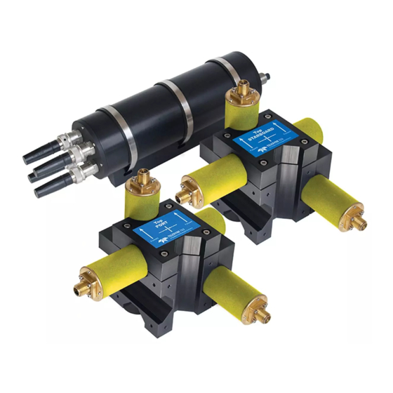
Three connection cables with waterproof connectors for the array of search-coils Subsea altimeter with connection cable and waterproof connector. This altimeter provides information for use by the entire Dualtrack system Figure B-1: Sub-sea components of the Teledyne TSS 350 System DPN 402197 Issue 7.1 © Teledyne Limited... -
Page 113: Physical Installation
Figure B-2: Sub-sea components of the Teledyne TSS 440 System Also included with the Dualtrack system but not shown are: Mounting components for the search-coils of the HydroPACT 350 system. ❐ Mounting components for the coil triads of the 350 system. -
Page 114: Electrical Connection
Altimeter port of the 440 SEP Figure B-3: Electrical interconnection of subsea components CAUTION To avoid damage to either of the SEPs, make certain that you fit the blanking plugs to any unused ports. DPN 402197 Issue 7.1 © Teledyne Limited B- 7... - Page 115 Failure to take this precaution might allow water to penetrate the SEP housings, following which total circuit failure will occur. Connect the Teledyne TSS 440 subsea components: 1. Route the coil connection cables to the correct ports on the 440 SEP. Use plastic cable clips to secure the cables to the fixed framework of the ROV.
-
Page 116: System Configuration
Note that the external logging file changes its format when you switch between the 440 and the 350 mode. Be aware that this might cause problems with the data logger and its software. DPN 402197 Issue 7.1 © Teledyne Limited B- 9... -
Page 117: Power Supply Requirement
Teledyne TSS has developed two levels of training course to provide for the needs of those who will be involved with a survey that uses the 350 system. For effective learning, the maximum number of participants in each course is limited. -
Page 118: C Cables And Tones
350 system to perform the survey. A tone generator can be supplied for use with the 350 system. Contact Teledyne Limited for advice if necessary. -
Page 119: Connection To The Cable
This represents a progressive short circuit that means less tone current flows at the far end of the cable than at the near end. The detection range of the 350 sys- tem depends upon the current flowing at the tone frequency. It follows therefore © Teledyne Limited DPN 402197 Issue 7.1... -
Page 120: Fibre-Optic Cables
If the far end of the cable is in the water, then the sea water itself can provide the signal return path. To use this method, you should attach a sacrificial anode to the exposed cable core and seal the cable against water ingress at the far end. DPN 402197 Issue 7.1 © Teledyne Limited C- 3... -
Page 121: D Coil Tester
The Coil Tester is used to confirm the 350 system is functioning in the correct manner. This is achieved by generating a localised and controlled alternating magnetic field. The Coil Tester provides the following benefits: A quick and simple method for testing the individual search coils of HydroPACT 350 system ❐ and the associated cables, connectors and circuitry. -
Page 122: Operation
If the parameters have changed, the new values will be downloaded to the SEP. D.2 Operation The Coil Tester is supplied with default settings of 25Hz. To change the frequency specified, see section D.2.1. DPN 402197 Issue 7.1 © Teledyne Limited D- 2... -
Page 123: Table D-1: 350 System Subsea Parameters
10. Note which coil is being tested. This will be defined on the attached connector cable, as out- lined in Table D-2 below. Table D-2: 350 System Connector Cable Identification Connector ID Description Starboard Vertical Starboard Lateral Port Vertical Port Lateral © Teledyne Limited DPN 402197 Issue 7.1... -
Page 124: Frequency Selection
Frequency Selection Switch. When supplied by Teledyne TSS, the Coil Tester will be set to its default position five and 25Hz. It is strongly recommended that a default test is carried out using this frequency setting. -
Page 125: Fault Identification
5. Press and hold down the power battery switch on the coil tester and confirm that the battery condition LED shows the battery to be in a good condition. The battery life for continuous use is estimated to be thirteen hours or three years in stand-by mode. © Teledyne Limited DPN 402197 Issue 7.1... -
Page 126: Maintenance
Weight (inc battery): 0.8kg Power Supply: PP3 9v, 550mA hours Power Consumption: 42mA @ 9V Tone Frequency: 25Hz (default) to 21Hz Waterproof: IP65 Battery Consumption - Constant Operation: 13 hrs Standby: 3 years DPN 402197 Issue 7.1 © Teledyne Limited D- 6... -
Page 127: E Reference
The following pages contain blank sample copies of forms that you may use to record details about the HydroPACT 350 system before and during a survey. You should complete these forms and include copies with the final survey results to help the post-processing engineers with their survey analyses. -
Page 128: Survey Details
Target Type: Magnitude of tone at source (mA): Tone frequency (Hz): Reminder interval (mins): Threshold setting (µV): Audible Alarm enabled? Survey Completed by: Teledyne TSS 350 Training Certificate No.: Date of training: DPN 402197 Issue 7.1 © Teledyne Limited E- 2... -
Page 129: F Index
Error sources 5-1 Vehicle pitch 5-3 Data Fields Vehicle position 5-2 Signal voltage 4-7 Vehicle roll 5-3 Data fields Errors Signal voltages 4-11 Interference 5-5 Target coordinates 4-6, 4-9 External logging format see Data logging DPN 402197 Issue 7.1 © Teledyne Limited... - Page 130 Tracked vehicle 5-8 Operating theory A-1 Video Overlay Oscilloscope 3-15 Setup 3-23 Power Dualtrack see Dualtrack Quality Control 3-13 Quality control 3-27 Envelope 3-28 envelope 7-2 flags 4-6 Run mode Coil drive 3-13 © Teledyne Limited DPN 402197 Issue 7.1...
- Page 131 © 2019 Teledyne Ltd. HydroPACT 350 User Manual Document Part Number: 402197 Issue: 7.1 Date: January 2019...
Need help?
Do you have a question about the HydroPACT 350 and is the answer not in the manual?
Questions and answers