Table of Contents
Advertisement
Quick Links
Advertisement
Table of Contents

Summary of Contents for Fliegl VFW
- Page 1 Operating instructions VFW vacuum tanker We are Fliegl.
-
Page 3: Customer Service
Language of original operating instructions: German (Translation of original operating instructions) Copyright Fliegl, 2020 All rights reserved. Reproduction, in whole or in part, is only permitted with the approval of Fliegl. We are constantly developing and enhancing our products and therefore reserve the right to make changes to them without prior notification. -
Page 4: Ec Declaration Of Conformity
Description and identification: Product: Fliegl vacuum tanker Type: VFW 3000, VFW 4000, VFW 5000, VFW 6200, VFW 7500, VFW 8600, VFW 10600, VFW 12000, VFW 14000, VFW 16000, VFW 18000, VFW 20000, VFW 22000, VFW 23000, VFW 25000, VFW 27500, VFW 30000... -
Page 5: Liability And Damages
Fliegl Agrartechnik GmbH assumes no liability for the use of other products and any resulting damage. No claims for modification of delivered products can be made on the basis of the information, images and descriptions provided in this manual. -
Page 6: Description Of The Machine
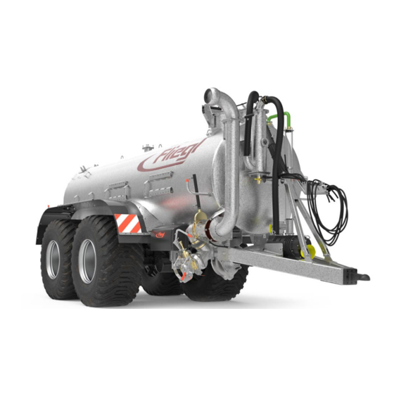
5. Description of the machine Functional description The drive shaft powers a compressor which generates negative pressure (vacuum) in the tank container. By connecting a suction hose to the quick coupler, the slurry can be sucked into the tank by means of the negative pressure. - Page 7 Layout of the machine The following figure provides an overview of the most important components and assemblies and shows where they are installed on the machine: Siphon & additional siphon (5.2.7) Pressure gauge (5.2.8)) Hydraulic gate valve Filling dome preparation (rear) (5.2.6) (5.2.4)
- Page 8 5.2.3 Manway (standard) The manway serves as an entry point for performing necessary repairs or cleaning work on the vacuum tanker. Fig. 4 Manway The container must be cleaned and well ventilated before/during any work in the tank. Open all gate valves and covers. The container must be depressurised. Caution: risk of suffocation in the case of insufficient cleaning or ventilation! 5.2.4 Hydraulic gate valve, rear (standard)
- Page 9 5.2.8 Pressure gauge (standard) The container pressure must be checked on a regular basis via the pressure gauge. Fig. 10 Pressure gauge Maximum container pressure 0.5 bar 5.2.9 Quick coupler (standard) The vacuum tanker can be filled by connecting a suction hose to the quick coupler.
- Page 10 5.2.14 Suction nozzle (optional) The suction nozzle – in combination with a docking station – enables convenient suction without having to leave the tractor cab. It is operated via the hydraulic control of the tractor or tank. Fig. 16 Suction nozzle 5.2.15 Hydraulic compressor changeover (optional) The suction/discharge function can be controlled from the tractor cab via the hydraulic compressor changeover.
-
Page 11: Transport And Installation
Weights – standard equipment Drawbar load (approx. kg) Total weight (approx. kg) Type Version Single- 3000 axle Single- 4000 axle Single- 5000 axle Single- 6200 axle Single- 7500 axle Single- axle 8600 Tandem Single- axle 10600 Tandem Single- axle 12000 Tandem Single- axle... -
Page 12: Preparation And Setup
7. Start-up Check before start-up Check to ensure that all safety devices (covers, panels etc.) are in proper condition and are attached to the trailer in protective position. Lubricate the tank trailer according to the lubrication schedule. Then check all screw connections specified below for tightness. Check the tyres to ensure the air pressure is correct (as per manufacturer specifications). -
Page 13: Hydraulic Brake System
Hand brake lever (overrun brake) – parking brake Applying the brake: To activate the hand brake, pull the actuating lever towards the drawbar eye. The brake locks automatically. Releasing the brake: Press in the button at the tip of the actuating lever to unlock the brake. Move the lever towards the container while keeping the button depressed. - Page 14 Installing forced steering on the towing vehicle (optional) The customer mast adapt the forced steering individually to each towing vehicle. This means that the settings must be re- adapted every time the towing vehicle is changed. The dimensions on the Ø 80 ball head coupling and the clearances according to ISO 500 and ISO 730 must be applied. Procedure Mounting of the steering cylinder at the same axial and vertical height as the ball head coupling on the towing...
-
Page 15: Electrical Systems
8.10 Electrical systems Before each journey, check to ensure the electrical light system is working properly. The tank trailer must only be used when the lighting system is connected and operational. Lighting connection Procedure: Power is supplied by the towing vehicle via plug connection(s). Plug connection for lighting (7-pin connector, ISO 1724) Fig. -
Page 16: Use And Operation
9. Use and operation Trailer operation 9.1.1 Setting up the trailer coupling on the towing vehicle Move the towing device of the towing vehicle to the correct height. Position the trailer coupling (A) on the towing vehicle so that the tank trailer is horizontal when it is hitched and so that, when the trailer is attached, there is sufficient space between the drive shaft and the drawbar (A1), especially during tight... - Page 17 General safety and operating instructions The following section contains some general notes on safety and operation for working with the tank trailer, repeated and summarized together for better clarity: In addition to the information in these operating instruction, you must also observe the generally applicable safety and accident prevention regulations.
- Page 18 Operation via control panel (control symbols) If your tanker features a hydraulic control block, specific functions are operated via a control panel. The following symbols represent the relevant functions. Fig. 36 Control panel Storage box – accessories Fig. 37 When disconnected, the control panel must be placed in the designated storage box to protect it against moisture.
- Page 19 Operation via tractor control units If the tanker does not feature a hydraulic control block, all functions are operated directly via tractor control units. Summary of tank functions with pressure sequence valve: If a pressure sequence valve is installed, the following 3 functions can be controlled with one tractor control unit: ...
-
Page 20: Recommended Working Speed
The suction valve opens. If the double-action control unit is operated in the other direction (direction 2), the functions are performed in reverse order. Fig. 43 Suction nozzle / suction valve Operating the turbo filler 9.7.1 Operation via tractor control unit An oil flow rate of approx. -
Page 21: Operation
Operation 9.9.1 Filling process Suction process via quick coupler: Connect the suction hose to the quick coupler. Open the suction valve by hand. Switch the compressor to suction via the compressor changeover. Switch on the drive shaft. Check the compressor oil level before starting! Verify that the oiler on the compressor is configured correctly. - Page 22 Optimum emptying can be ensured by raising the tank tipping cylinder. Sprinkler nozzle (special equipment) 9.9.3 Fliegl vacuum tankers can not only be equipped with a compressor, but also with a combination of compressor and centrifugal pump. In this case, the compressor is primarily used to suck in the substrate, while the centrifugal pump is responsible for the discharge process via the sprinkler nozzle.
-
Page 23: Operational Maintenance
Operational maintenance 10.1 General instructions for maintenance Operational maintenance helps to ensure trouble-free and efficient use of the machine. Operating personnel can perform this work after receiving appropriate instruction. Maintenance task Interval Lubricate all lubrication points on the trailer (see lubrication schedule) Check all screw connections on the chassis and attachment as well as the mounting points of the drawbar eyes and balls to ensure they are securely fastened Check tyre pressures... - Page 24 10.1.2 Lubrication schedule – body Lubricants Standard Greases DIN 51 502, KP 2K Vane lubricating oil ISO VG 68 / ISO VG 100 (note maintenance plan) Transmission gear oil ISO VG 220 / ISO VG 460 (note maintenance plan) Lubricating point – hydraulic filling dome Lubricating nipple –...
- Page 25 Compressor – maintenance plan (brief overview) Hertell KD series Battioni MEC series Vane lubrication Vane lubricating oil: ISO VG 68 Vane lubricating oil: ISO VG 100 Lubrication is performed in conjunction with the oil pump Pressure lubrication (standard) takes place both during the during the vacuum and pressure phase.
- Page 26 Compressor – maintenance plan (brief overview) Hertell KD series Battioni MEC series Transmission gear lubrication Transmission gear oil: ISO VG 220 Transmission gear oil: ISO VG 460 The gear unit must be filled with oil up to the specified level The gear unit must be filled with oil up to the specified level (sight glass E).
- Page 27 Lubrication schedule – rigid axle Interval Off-road use Brake shaft bearing, outside and inside Outside Europe Manual slack adjuster Off-road use Automatic slack adjuster Outside Europe Off-road use Change wheel hub grease, check taper roller bearing and shaft sealing ring for wear Outside Europe Conventional hub bearing Maintenance plan –...
-
Page 28: Tyres And Wheels
Maintenance plan – steering axle Interval Standard LA Standard HLL Check wheel nuts are securely fastened and retighten if necessary Check the wheel hub bearing play; adjust if necessary Check the brake lining thickness Check brake setting on slack adjuster and adjust if necessary Check brake setting on automatic slack adjuster and adjust if necessary Functional check of automatic slack adjuster Check that the caps are secure... - Page 29 10.1.6 Maintenance of the compressed air brake system Draining water from the air reservoir: Every day, the water must be drained from the compressed air reservoir by pulling on the ring on the underside. Line air filter The two filter housings (1) contain sieve inserts (3). If the filter inserts in the line air filters are clogged, air flows around them without being filtered.
- Page 30 10.1.8 Adjusting the overrun brake (tandem) Fig. 58 Overrun brake mechanism Procedure Position the tank trailer on solid, level ground. Use the supplied wheel chocks to secure the tank trailer against rolling away. Raise the axle off the ground. Set the overrun mechanism and parking brake to release position. Release the turnbuckle (A).
- Page 32 Fliegl Agrartechnik GmbH Bürgermeister-Boch-Str. 1 D-84453 Mühldorf a. Inn Tel.: +49 (0) 86 31 307-0 Fax: +49 (0) 86 31 307-550 e-Mail: info@fliegl.com 1-006B06201.0...
Need help?
Do you have a question about the VFW and is the answer not in the manual?
Questions and answers