Advertisement
Quick Links
Advertisement

Related Manuals for CNC Seig X2

Summary of Contents for CNC Seig X2
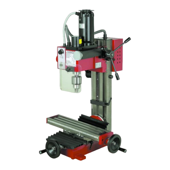
- Page 1 Assembly Instructions for Seig X2 and X2D Benchtop Mini MIll...
- Page 2 This kit has been developed over the past three years with ease of installation, functionality and dependability giving your Seig X2 or X2D benchtop mini mill full three axis capabilities. In addition, it can support the addition of a fourth axis if you desire. (Software used by customer must have fourth axis capabilities...
- Page 3 For this installation you will need the following: Metric hex key set SAE hex key set Phillips screwdriver Flat screwdriver Small adjustable wrench Deadblow or rubber hammer Lithium grease (any grease will do but lithium is recommended) An electric drill To prepare the machine, if new, please remove all the rust prohibitive applied by the factory.
- Page 4 The kit will arrive assembled. All thrust bearings will be adjusted. Note: thrust bearings are designed to eliminate or reduce axial slack. They are not intended to be over tightened. They are pre-set in assembly. The stepper motor can be mounted on either end. As delivered, it is set up to be on the left side of the table (looking at the machine).
- Page 5 Let’s start by removing the table. First, remove the screw or nut holding the crank handle from the lead screw. Then remove the two bolts that hold the right side table endplate from the table, then the two bolts that hold the left side table endplate from the table Now loosen the jam nuts that hold the gib in place.
- Page 6 Now, remove the two bolts that hold the lead screw nut in the Y axis cross slide. Be sure and mark these two bolts as you will need them later for re-assembly. You should be able to lift the lead screw and nut up from the base.
- Page 7 It’s now time to remove the Y axis cross slide. Remove the screw or nut from the cranking handle. Then remove the two bolts that hold the bearing housing from the front of the base Then remove the bolt that holds the Y axis lead screw nut from the cross slide casting.
- Page 8 Let’s remove the cross slide base casting from the machine base. Loosen the jam nuts from the gib adjustment screws and back out the gib adjustment screws as before. The are located on the right side of the Y axis cross slide casting.
- Page 9 Now let’s remove the Z axis rack gear. For this you will need some assistance, or a way to stabilize the headstock, possible some wooden blocks or some small machinist jacks. You will be moving the head up and down using the handles on the fight side of the head.
- Page 10 To remove the rack gear, you will first need to remove the spindle motor and mount from the headstock, There are 4 bolts that you will need to remove that are located on the top of the motor mounting plate. Gently, and carefully, raise the spindle motor and mount from the head.
- Page 11 Now, raise the head to expose the remaining screws on the rack. This is where you will need to secure the head in place. The next step will remove the ability to raise or lower the head using the Z axis cranking levers. Wooden blocks or jacks between the spindle and the table, Or, raise the provided clamp to the bottom of the head...
- Page 12 With the headstock securely clamped in place, the remaining screws removed from the rack gear, rotate the head Pull rack upwards raising/lowering levers to raise the rack gear from the top of Until it clears the column and remove it. It is no longer needed. The column...
- Page 13 Exploded view if the headstock You will be removing the small Phillips screws Remove the set screw that holds the crank levers in place and pull it off, it is no longer needed Then remove the thin metal cover The remove the housing that holds the pinion gear, remove the pinion Refer to drawing on next slide...
- Page 14 You will now remove the Z axis head raising/lowering assembly. Note: once removed, you may no longer raise or lower the head with the cranking levers. Start by removing the set screw that locks the handle assembly to the pinion gear that goes through the head.
- Page 15 Align the holes in the clamp bar and Clamp bar….slide it inside the column. use the screws provided, attach it to Note, there is a 3/8-16 tapped hole in the column by putting the screws top of this bar. It must go up! This bolt is into the holes on the column that the also useful to hold the bar while rack gear was attached to.
- Page 16 At this point, you are ready to start re-assembling the machine with the conversion kit. There is no definite way to re-assemble so you can start where ever you choose. But for the instructions, we will do the Y axis cross slide to the base first.
- Page 17 This example shows the machine base only. Your column should be attached. You will need access to the bottom of the base and raised so that you can insert the Y axis ball screw assembly through the bottom of the base into the hole at the front of the casting.
- Page 19 Slide the Y axis cross slide casting onto the machine base. Insert the gib that you previously marked Y axis, then, if you removed the gib adjustment screws, re-insert them into the right side of the Y axis cross-slide casting (not shown) but the are located here Do not tighten at this point, screw in just enough to engage the gib.
- Page 20 Now, install the X axis ball screw and nut. This is the point where you need to decide which side of the table that you want to mount the stepper motor. This is shown with a left sided mount. If you decide to mount it on the right side, you will need to remove the ball nut from the screw and reverse.
- Page 21 Using the two screws that you removed to free the X axis lead screw nut from the Y axis cross slide base, re-insert them through the ball nut mount and into the Y axis cross slide base. Note the orientation of the nut…the recirculation tubes are on the bottom side of the nut.
- Page 22 Table front Carefully slide the table into the dovetails of the Y axis cross slide. Make sure the table front is on the correct side facing out. It can be identified by have a measuring scale on it!! Note: it can be installed from either side.
- Page 23 Some grinding may be required!!!!
- Page 24 Note: VERY IMPORTANT!!!! The dovetails on the table are offset from the center of the table top as shown here. The table end plates can be installed either way, and, differently at each end of the table. The large hole in the table end plate is off set to match the dovetails but the holes that mount it to the table are in the center of the table.
- Page 25 Re-install the thrust bearings, nylok nut and stepper motor mount on the threaded end of the ball screw. Do not tighten the bolts at this point. Install the ball nut receiver making sure the roller support bearing is in the receiver. Do not tighten the bolts at this poing...
- Page 26 It’s not time to install the Z axis assembly. This will be much easier since it is shipped assembled and, all you have to do is remove the lift rod and slip the assembly down on to the top of the column. You may have to rotate the ball nut to raise or lower the head lift assembly to fit over the sides of the head.
- Page 27 The column clamp bar is already inside the column...
- Page 28 Slide the Z axis assembly down on top of the column. With the column top plate setting on the top of the column, move it around until the 3/8-16 threaded hold is in the slot on the top of the column top plate. Thread the 3/8-16 bolt that is provided into the column clamp bar with the washer provide.
- Page 29 Rotate the ball nut and lower the ball screw down until the holes in the end of the side plates align with the holes in the side of the head that were left when you removed the rack and pinion from the headstock...
- Page 30 Insert the Z axis head lift pin into the 5/8” hole in the headstock. This is the hole that the pinion gear shaft fit into at dis-assembly. Now, move the side plates Down until the holes align, insert the shoulder bolt provided through the side plate and into the lift pin.
- Page 31 At this point, the machine is assembled and is ready to make final adjustments. If you desire, you can install your steppers and controls. However, it may be a good idea to install the shaft couplings on the end of the X and Y ball screw shafts.
- Page 32 Axis Adjustment Procedure for X and Y At this point, the machine is roughly assembled needing final adjustments. 1. X axis – move the axis with the drill and let it self align. It may stick at first but it will improve with each movement.
- Page 33 The following slides are instructions for fine tuning the machine axis for movement. Before you start, you will need: An electric drill Some grease – lithium is best but really, any grease will do. Your hex key wrenche A small adjustable wrench (Crescent) Some good music And a lot of patience Also, please refer to your machines operators manual for adjustment of the gibs.
- Page 34 Axis Adjustment Procedure for X and Y Y axis adjustment 1. Using the drill and coupling again, slowly move the Y axis back and forth. Apply grease as before. 2. Move the table all the way to the front of the machine. Tighten the stepper mount. 3.
- Page 35 Axis Adjustment Procedure for X and Y Z axis adjustment 1. Unfortunately, you will not be able to use a drill for this one. It is recommended that you wait until the Z axis stepper motor is installed and capable of being moved by the controls that you have installed. 2.
Need help?
Do you have a question about the Seig X2 and is the answer not in the manual?
Questions and answers