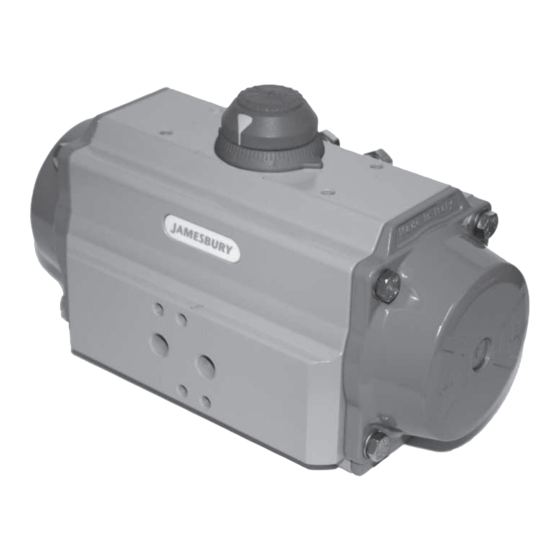
Summary of Contents for Mesto jamesbury Valv-Powr VPVL
- Page 1 Valv-Powr® VPVL Mod D Value-Line® Double-Opposed Piston Actuators Installation, Maintenance and Operating Instructions...
-
Page 2: Table Of Contents
IMO-553 EN TABLE OF CONTENTS GENERAL ..............3 1.1 Warning ................3 TECHNICAL DATA ............. 3 INSTALLATION ............4 3.1 General ................4 3.1 Operation ................. 4 MAINTENANCE ............4 4.1 General ................4 4.2 Disassembly ..............4 4.3 Assembly ................6 SAFETY LOCKOUT DEVICE ........ -
Page 3: General
IMO-553 EN GENERAL TECHNICAL DATA This instruction manual contains important information 1. Operating Media: Dry or lubricated air, non-corrosive regarding the installation, operation, and troubleshoot- and inert gas, or light hydraulic oil. ing of the Jamesbury® Valv-Powr VPVL Mod D Value-Line 2. -
Page 4: Installation
IMO-553 EN When disassembling VPVL actuators, use caution and be certain that the actuator is free from accessories and the air INSTALLATION supply is disconnected. When the actuator is a springreturn unit, make sure that the actuator is in the failed position General before disassembling. - Page 5 IMO-553 EN Lift position indicator (19) off shaft; it may be C. Remove end-cap o-rings (14) and discard if replacing necessary to pry gently with a screwdriver. all soft parts. 2. Removal of Stop Cap Screws (02), (Figure 4): 4. Piston (40) Disassembly, (Figure 6): A.
-
Page 6: Assembly
IMO-553 EN Assembly TABLE 2 Prior to assembly, ensure that all components are clean Recommended VPVL Lubricants and undamaged. General Use Dow Corning type Molykote® G-2003 NOTE: (Table 2) lists the recommended Valv-Powr lubricants. Dow-Corning Silicone 111 O-Ring Areas (For Standard and High Temperature) 1. - Page 7 IMO-553 EN C. Hold the body (50) in a horizontal position by insert- F. Press the two pistons (40) simultaneously into the ing the top of the shaft in a vice, or inserting the bot- body (50) until the piston racks are engaged and tom of the shaft connection into a male drive fitted rotate the body clockwise (if viewing the bottom of into a vice as shown by (Figure 10).
- Page 8 IMO-553 EN 4. Assembly of Stop Screws (2) and Stroke Adjustment. (Figure 17): A. Insert the nut (4), washer (3), and o-ring (11) onto the stop screws (2). Figure 14 B. Screw the stop screws (2) into the body (50). External Travel Stop Adjustment, (Figure 17): 2, 4, 3 and 11 Figure 15...
- Page 9 IMO-553 EN D. Cycle the actuator/valve to the counter-clockwise end of travel and measure to determine if the valve is in the proper position. (In most applications this will 19.5 be fully opened.) E. If the valve is not in the correct counter-clockwise position, turn the left stop adjustment screw (2) IN to reduce actuator travel, or OUT to increase actuator 19.1...
-
Page 10: Safety Lockout Device
IMO-553 EN SAFETY LOCKOUT DEVICE Double Acting Actuators: A. Back off one travel stop screw, leaving it partially threaded in the end cap. Entirely remove the other stop screw from the other end cap. WARNING: B. Open valve using air pressure. NOTE: Actuator will IF THE SERIAL NUMBER OF THE ACTUATOR IS 10136023 OR LOWER leak due to removed travel stop. -
Page 11: Actuator Storage
IMO-553 EN Figure 22 3. Assembly of Safety Cover and Padlock: A. Insert the Safety Cover (229) between the Special Figure 21 Nuts (228) and Washer (03) as shown in (Figure 22). B. Then insert in the hole of the Safety Cover the Padlock (230) and lock it. -
Page 12: Exploded View
IMO-553 EN EXPLODED VIEW Figure 23... -
Page 13: Parts List
IMO-553 EN TABLE 3 - PARTS LIST FOR (FIGURE 23) Part # Part Description Material Octi-Cam (Stop Arrangement) Stainless Steel / Carbon Steel (1) Stop Cap Screw Stainless Steel Washer (Stop Cap Screw) Stainless Steel Nut (Stop Cap Screw) Stainless Steel Bearing (Piston Back) High Grade Polymer Bearing (Pinion Top) - Page 14 IMO-553 EN TABLE 4 VPVL END CAP TORQUE VALUES End Cap Metric Torque Torque Torque Bolt Size Wrench Size in-lbs ft-lbs VPVL051 VPVL100 VPVL200 VPVL250 VPVL300 VPVL350 VPVL400 VPVL450 VPVL500 VPVL550 VPVL600 VPVL650 VPVL700...
- Page 15 IMO-553 EN HOW TO ORDER To specify a complete Valv-Powr Value-Line® Actuator, simply make a selection from the code boxes below. EXAMPLE: VPVL 400 SR4/5 B AS D, shown below, is a 59 FT•LBS 60-psi (84 N•m @ 4.2 bar) spring-return actuator with spring-to-close rotation, hard-anodized PTFE-coated body, polyester-coated end caps, standard temperature rating, and 100% adjustable travel stops.
- Page 16 IMO-553 Subject to change without prior notice. Metso Flow Control Inc. Europe, Vanha Porvoontie 229, P.O. Box 304, FI-01301 Vantaa, Finland. Tel. +358 20 483 150. Fax +358 20 483 151 North America, 44 Bowditch Drive, P.O. Box 8044, Shrewsbury, M A 01545, USA. Tel. +1 508 852 0200. Fax +1 508 852 8172 South America, Av.


Need help?
Do you have a question about the jamesbury Valv-Powr VPVL and is the answer not in the manual?
Questions and answers