
Related Manuals for Yujin Robot YRL3V2 Series


Summary of Contents for Yujin Robot YRL3V2 Series
- Page 1 YUJIN 3D LiDAR YRL3V2 Series YRL3V2-05 / YRL3V2-10 / YRL3V2-25 User Guide Revision: 1.0 Date: 2022/04...
- Page 2 Even in the hypothetical event that Yujin Robot was aware of the possibility of any damages ahead of time, Yujin Robot assumes no responsibility for errors, omissions, or damages that may arise from the information contained in this document.
- Page 3 Change History Change History The following table contains version information for this document and a history of significant changes. Version Date of Writing Changes V1.0 03/07/2022 First Rlease...
-
Page 4: Table Of Contents
YRL3V2 Series User Guide Table of Contents 1. Safety Information 1.1 Definition 1.2 General Safety 1.2.1 Precautions for Installation 1.2.2 Precautions for Use 2. Introduction 2.1 Product Overview 2.2 Product Features 2.3 Applications 2.4 System Diagram 3. Before Using YUJIN LiDAR 3.1 Measurement information 3.2 Scanning Range (4 Scanning Modes) 4. Installing YRL3V2 4.1 Components 4.2 Product Dimensions... - Page 5 Table of Contents 5.9 View Settings 5.9.1 Orthographic Projection/Perspective Projection settings 5.9.2 Rotational View/Top View/Side View settings 6. Maintenance and Troubleshooting 6.1 Cleaning and Maintenance 6.2 Troubleshooting 7. Product Specifications 7.1 Basic Specification 7.2 Performance 7.3 Interface 7.4 Environmental Specifications 8. Appendix 8.1 Appendix A. Driver Interface (API) 8.1.1 Parameters 8.1.2 Parameter Input/Output 8.1.3 Data Output 8.2 Appendix B.
-
Page 6: Safety Information
YRL3V2 Series User Guide 1. Safety Information 1.1 Definition The guidelines below are provided to ensure user safety and prevent property damage. Please read the information carefully to ensure the safe use of the product. Warning Users must follow these guidelines to prevent hazardous situations that can lead to serious injury or death. - Page 7 Introduction Do not use this product in places that may cause injury, death, or property damage. • Interference or contact between different laser light sources may cause abnormal operation of the • sensor. Do not use it in outdoor environments, dusty places, humid places, or in direct sunlight. •...
-
Page 8: Introduction
YRL3V2 Series User Guide 2. Introduction 2.1 Product Overview YRL3V2 is a single-channel 360-degree 3D scanning ToF (Time of Flight) laser sensor. It measures the distance to surrounding objects and provides point clouds for accurate mapping. YRL3V2 provides 4 scanning modes for autonomous mobile robots (AMRs) to optimize SLAM based mapping and navigation. -
Page 9: System Diagram
Introduction 2.4 System Diagram The YRL3V2 system consists of YRL3V2, power supply, and Customer PC or Mobile Robot. YRL3V2 is provided with a power cable (1 m) and an Ethernet cable (1 m). The power supply, PC or Mobile Robot must be purchased separately by the user. LiDAR Viewer, a software for running LiDAR, is also available. With the LiDAR Viewer, you can monitor the status of the LiDAR and configure basic settings. -
Page 10: Before Using Yujin Lidar
YRL3V2 Series User Guide 3. Before Using YUJIN LiDAR 3.1 Measurement information YRL3V2 can collect more than 30,000 point clouds per second. One point cloud contains the following information: Horizontal Angle: Horizontal angle measured (-180º–+180º) • Vertical Angle: Vertical angle measured (-40º–+40º, max 80º) •... -
Page 11: Scanning Range (4 Scanning Modes)
3.2 Scanning Range (4 Scanning Modes) YRL3V2 supports 4 scanning modes optimized for autonomous mobile robots (AMRs). Please refer to the horizontal and vertical scanning ranges in each mode. Upper Upper Upper Upper Horizontal Horizontal Horizontal Horizontal ���° ���° ���° ���° Horizontal Horizontal Horizontal... -
Page 12: Installing Yrl3V2
YRL3V2 Series User Guide 4. Installing YRL3V2 4.1 Components The components are packaged in individual boxes. Please check the components upon arrival of the product. • YRL3V2 series product • 1 m power cable • 1 m ethernet cable • Quick start guide... -
Page 13: Component Details
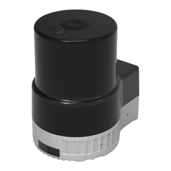
Installing YUJIN LiDAR 4.3 Component Details The product consists of optical section and bottom section, and please refer to the diagram below for details. Optical Bottom Fig. 4: YRL3V2 Component Details Optical screen Ethernet cable Central cover Power cable gland Bottom cover Ethernet cable gland LED label Axis adjustment mark (0°... -
Page 14: Installing The Product
YRL3V2 Series User Guide 4.4 Installing the Product 4.4.1 Choosing the installation location In order to achieve optimal performance, we recommend you install the LiDAR in a place that meets the requirements below. For efficient heat dissipation, install the product on materials with high thermal conductivity •... -
Page 15: Connecting The Cables
Installing YUJIN LiDAR 4.5 Connecting the Cables YRL3V2’s two integrated cables are 27 cm long and can be used by connecting them with the power cable (1 m) and Ethernet cable (1 m) provided with the product. If you need to extend the cable, please contact our Technical Support. -
Page 16: Cable Pinout Guide
YRL3V2 Series User Guide 4.5.2 Cable Pinout Guide Power Input Connector Ethernet RJ45 Connector • • RJ45 Pin No. Signal MOLEX: 39-01-4030 Pin No. Signal Color Red & White +12V Black IP PWR Connector IP PWR EXTENSION Connector • • L102-M8-H0401 (Male) L102-M8-T0402-01 (Female) Pin No. -
Page 17: How To Start/Stop Lidar
Using YUJIN LiDAR Viewer 4.6 How to Start/Stop LiDAR LiDAR maintains a standby state until it is connected to the host PC and does not operate. You can connect through the LiDAR Viewer or LiDAR driver to start the operation. 1. To start LiDAR: Click the [Create IP Connection] button on the LiDAR viewer software to connect LiDAR to the host •... -
Page 18: Using Lidar Viewer
YRL3V2 Series User Guide 5. Using LiDAR Viewer 5.1 LiDAR Viewer Overview LiDAR Viewer Software displays YRL3V2’s point cloud data on the screen in real time. You can use the software in Ubuntu OS. How to enter commands in Ubuntu OS: Run “ctrl +alt + t” on the desktop to enable the Terminal •... -
Page 19: Setting Up The Network
Using YUJIN LiDAR Viewer 5.2 Setting Up the Network 1. Click the [Network] icon in the upper right corner of the monitor screen. Select [Wired Settings]. 2. Click [Network] in the menu on the left. Click the [Settings] icon in the Wired menu. 3. - Page 20 YRL3V2 Series User Guide 4. Set the ON/OFF switch to OFF and set it back to ON to reset the network . 5. View the newly assigned static IP address. 192.168.1.37...
-
Page 21: Running Lidar Viewer
Using YUJIN LiDAR Viewer 5.3 Running LiDAR Viewer Enable the Terminal window on the desktop and enter the LiDAR Viewer execution command. 1. Launch the Terminal window and enter the command below to install QT5. sudo apt-get install qt5-default • 2. Go to the provided LiDAR Viewer software location. Command: cd ~/Downloads/viewer_v2_x.x.x/ (where LiDAR Viewer was installed by the user) •... -
Page 22: Connecting Lidar
YRL3V2 Series User Guide 5.4 Connecting LiDAR Caution The default network setting the value of LiDAR was set to 192.168.1.250 at the factory. When connecting multiple LiDARs, each LiDAR must be connected to the Host and then assigned a different IP address. -
Page 23: User Interface
Using YUJIN LiDAR Viewer 5.5 User Interface When you launch LiDAR Viewer, the following user interface screen will appear: When the viewer is connected to LiDAR, point cloud data is displayed on the screen in real time. Users can set the data to be displayed on the screen. Item Description Top bar... -
Page 24: Ethernet Board Firmware Update
YRL3V2 Series User Guide 5.6.1 Ethernet Board Firmware Update 1. Enter LiDAR IP Address and click [OK]. 2. Click [open] under Ethernet Board FW Update. Select the downloaded Ethernet Board Firmware file. 3. Update the Ethernet Board Firmware by clicking [Save]. -
Page 25: Main Board Firmware Update
Using YUJIN LiDAR Viewer 5.6.2 Main Board Firmware Update 1. Click [Open] under the Main Board FW Update. Select the downloaded Main Board Firmware file. 2. Update the Main Board Firmware by clicking [Save]. -
Page 26: Sensor Configuration
YRL3V2 Series User Guide 5.7 Sensor Configuration You can connect to YRL3V2 and set the sensor data to be displayed on the viewer. Select the following tab to open a new window where you can make detailed settings: Item Description Set the IP address to use. (Initial value: 192.168.1.250) If the connection is established normally, the status value changes to “Connected,”... - Page 27 Using YUJIN LiDAR Viewer Item Description Set the LiDAR position to be displayed on the viewer screen. Use the arrow key or keypad to adjust the settings. The relative position of the LiDAR from the origin of the coordinate plane on the viewer screen is displayed. X: X-coordinate value (m) •...
-
Page 28: Visualization Settings
YRL3V2 Series User Guide 5.8 Visualization Settings You can set the point cloud data to be displayed on the LiDAR viewer. Select the following tab to open a new window where you can make detailed settings: Item Description Point cloud Color Mode: Set the color mode for the point cloud. -
Page 29: View Settings
Specifications 5.9 View Settings You can make settings for the viewer screen. 5.9.1 Orthographic Projection/Perspective Projection settings Select the projection mode from the menu tab. Item Description Orthographic Displays the 3D environment without a sense of depth. Used to measure Projection LiDAR performance. Perspective Default option. -
Page 30: Maintenance And Troubleshooting
YRL3V2 Series User Guide 6. Maintenance and Troubleshooting 6.1 Cleaning and Maintenance LIDAR requires periodic inspection and maintenance. Maintenance activity: Remove water and dust from the surface of LiDAR with a soft clean cloth. • Be careful not to cause damage (scratches or nicks) to the laser cover while performing maintenance. -
Page 31: Product Specifications
Product Specifications 7. Product Specifications 7.1 Basic Specification Model Name YRL3V2-05 YRL3V2-10 YRL3V2-25 10 m 25 m Detection Range (90% light remission) (90% light remission) (90% light remission) Size 65 mm x 85 mm x 91.4 mm (2.55" x 3.34" x 3.59") Weight 410 g (0.90 lbs) Power Consumption... -
Page 32: Interface
YRL3V2 Series User Guide 7.3 Interface Communication Interface 100 Mbps Ethernet Optical Indicators 1 x LED (Green: Available, Red: Error) Protocol UDP packet Configuration Software YUJIN LiDAR Viewer Horizontal Angle, Vertical Angle, Range, Intensity, Cartesian Output Data coordinates (x, y, z) -
Page 33: Appendix
Appendix 8. Appendix 8.1 Appendix A. Driver Interface (API) The API provided when the YRL3V2 driver is installed can be used for processing and collecting the scanned data. 8.1.1 Parameters The descriptions of the values used by the API are as follows. Parameter Name Default Description IP address for creating the communication... - Page 34 YRL3V2 Series User Guide Parameter Name Default Description Vertical angle upper limit for processing output mMaxVertiAngleParam pi*2/9 data (Unit: radian) Vertical angle lower limit for processing output mMinVertiAngleParam –pi*2/9 data (Unit: radian) Horizontal angle upper limit for processing mMaxHoriAngleParam output data (Unit: radian)
-
Page 35: Parameter Input/Output
Appendix 8.1.2 Parameter Input/Output These features are used to import or change values through the API. Parameter Name Unit Description void SetIPAddrParam (const Set the IP address for creating the std::string &ipAddr) communication socket Get the IP address for creating the string GetIPAddrParam() communication socket void SetPortNumParam (const... - Page 36 YRL3V2 Series User Guide Parameter Name Unit Description void SetExtrinsicTransformMatParam (const float x, const float y, Set the Transform Matrix for processing output m, degree const float z, data const float rx, const float ry, const float rz) void GetExtrinsicTransformParam (float &x,...
-
Page 37: Data Output
Appendix 8.1.3 Data Output These features are used to check the status and data of YRL3V2 through the API. Output Function Name Explanation int GetCartesianOutputsWithIntensity(double _SystemTime, std::vector <float>& _IntensityArray, Get the reflection intensity measured std::vector <float>& _XCoordArray, and 3D orthogonal coordinates std::vector <float>&... -
Page 38: Appendix B. Problems And Solutions
YRL3V2 Series User Guide 8.2 Appendix B. Problems and Solutions Describes the problems and solutions that may occur while using the robot. 8.2.1 Error Code Classification Symptom Solution User Error Code Error Power Error Contact Customer Service Horizontal Operation Error Contact Customer Service... - Page 39 Yujin Robot Co., Ltd. Harmony-ro 187 beon-gil 33, Yeonsu-gu, Incheon (Songdo-dong) www.yujinrobot.com Phone +82 32 550 2300 Fax +82 32 550 2301...
Need help?
Do you have a question about the YRL3V2 Series and is the answer not in the manual?
Questions and answers